


Making Measurements
Measuring Pulse Width
3
3-25
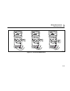
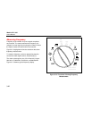
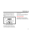
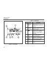
To measure duty cycle, set up the meter to measure
frequency; then press N a second time. You can
select the level the meter uses by pressing [ to
trigger on the positive slope or ] to trigger on the
negative slope. A typical duty cycle display is shown in
Figure 3-16.
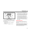
tc027f.eps
Figure 3-16. Duty Cycle Display
For 5 V logic signals, use the 5 V dc range. For 12 V
switching signals in automobiles, use the 50 V dc range.
For sine waves, use the lowest ac or dc range that does
not result in multiple triggering. A manually-selected lower
input range will often measure better than the AUTO-
selected input range.
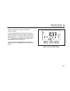
If a duty cycle reading is unstable, press M until the
AVG annunciator comes on and the average reading
appears in the secondary display.
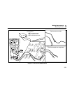
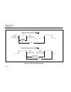
Measuring Pulse Width
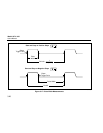
The pulse width function allows you to measure the
amount of time a signal is high or low within a given
period. See Figure 3-17. The measured waveform must
be periodic; its pattern must repeat at equal time intervals.