


Configure Your Sy
stem
Configure Your
System
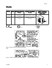
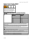
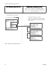
1. Select a Bas
e Model
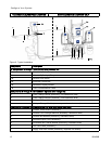
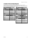
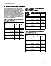
Choose a PD2K base model that meets your
application’s requirements. See Models, page 3 .
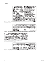
Base models i
nclude components A through F shown
in the Typic
al Installation drawing on the next page.
Base unit components are described in the following
table.
Component
Descriptio
n
Fluid Pump
s (A, B)
Thebasemo
dels include two fluid pumps, one for resin and one for
catalyst.
Install in the non-hazardous area.
Solvent Flow Switch (C) Confirms solvent flow to gun during purge.
Electrical Control Box (D) The electrical control box includes a barrier board, intrinsically safe
isolation board, 24 Vdc and 48 Vdc power supplies, Enhanced
Fluid Control Module, and Pump Control Modules. The Gateway
communication module, shipped separately, is installed in the electrical
control box. It accepts 90–250 Vac line power and converts that power to
acceptable low voltage signals used by other system components. Install
the electrical control box in the non-hazardous area.
Advanc
ed Display Module (E)
The Adv
anced Display Module (ADM) enables the user to setup, monitor,
and con
trol the system. Install the ADM in the non-hazardous area.
CAN cable (F) The CAN cable connects the Gateway communication module to theIS
remote mix control module.
332458B
11