


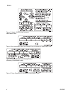
System Control D
rawing 16P577
System Contro
l Drawing 16P577
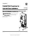
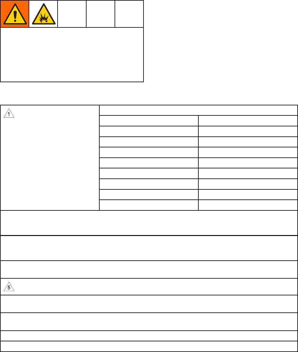
Do not substitute or modify system components
as this may impair intrinsic safety. For installation,
maintenance, or operation instructions, read
instruction manuals. Do not install equipment
approved only for non-hazardous location in a
hazardous location. See the identification label for
the intrinsic safety rating for your model.
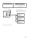
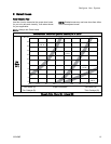
NOTES FOR SYSTEM CONTROL DRAWING 16P577 (FM13ATEX0026 SYSTEM ASSEMBLY
CERTIFICATE)
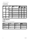
Alternate
M12 CAN Cables, for Hazardous Locations
Cable Part No. Length ft (m)
16V423
2.0 (0.6)
16V424
3.0 (1.0
)
16V425
6.0 (2.0)
16V426
10.0 (3.0)
16V427
15.0 (
5.0)
16V428
25.0 (8.0)
16V4
29
50.0 (16.0)
16V430
100
.0 (32.0)
2. The non-intrinsically safe terminals (power rail) must not be connected to any device which uses or
generates more than Um = 250 Vrms or dc unless it has been determined that the voltage has been
adequately isolated.
3.
The electrical enclosure ground screw must be connected to a true earth ground using the supplied
gr
ound strap (223547) or by an equivalent 10 AWG or larger isolated conductor. Resistance from the
e
lectrical enclosure ground to the true earth ground shall not exceed 1 ohm.
4. Multiple earthing of components is allowed. Intrinsically safe apparatus provides isolation from earth to
500 Vrms.
Do not operate system with power barrier cover removed.
6. Installation should be in accordance with ANSI/ISA RP12.06.01 “Installation of Intrinsically Safe Systems
for Hazardous (Classified) Locations” and the National Electrical Code® (ANSI/NFPA 70).
7. Installation in Canada should be in accordance with the Canadian Electrical Code, CAS C22.1, Part I,
Appendix F.
8. For ATEX, install per EN 60079–14 and applicable local and national codes.
9. For IECEx install per IEC 60079–14 and applicable local and national codes.
332458B 9