


Electrical Supp
ly
Electrical Su
pply
Improper wiring may cause electric shock or other
serious injury if work is not performed properly. All
electrical wiring must be completed by a qualified
electrician and comply with all local codes and
regulations.
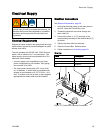
Electrical Requirements
Enclose all cables routed in the spray booth and high
traffic areas in conduit to prevent damage from paint,
solvent, and traffic.
The unit operates with 90-250 VAC, 50/60 Hz input
power, with a maximum of 7 A current draw. The
power supply circuit must be protected with a 15 A
maximum circuit breaker.
• A power supply cord compatible to your local
power configuration is not included. Wire gauge
size must be 8-14 AWG.
• The input power access port is 22.4 mm (0.88
in.) in diameter. A strain relief is provided which
accepts a cord diameter of 0.157–0.354 in. (4–9
mm). If another cord size is used, a user-supplied,
appropriate size strain relief must be installed.
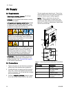
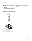
Electrical C
onnections
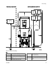
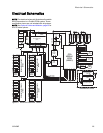
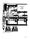
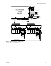
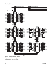
See Electrical Schematics, page 29.
1. Verify that
electrical power at the main panel is
shut off. Op
en the Control Box cover.
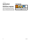
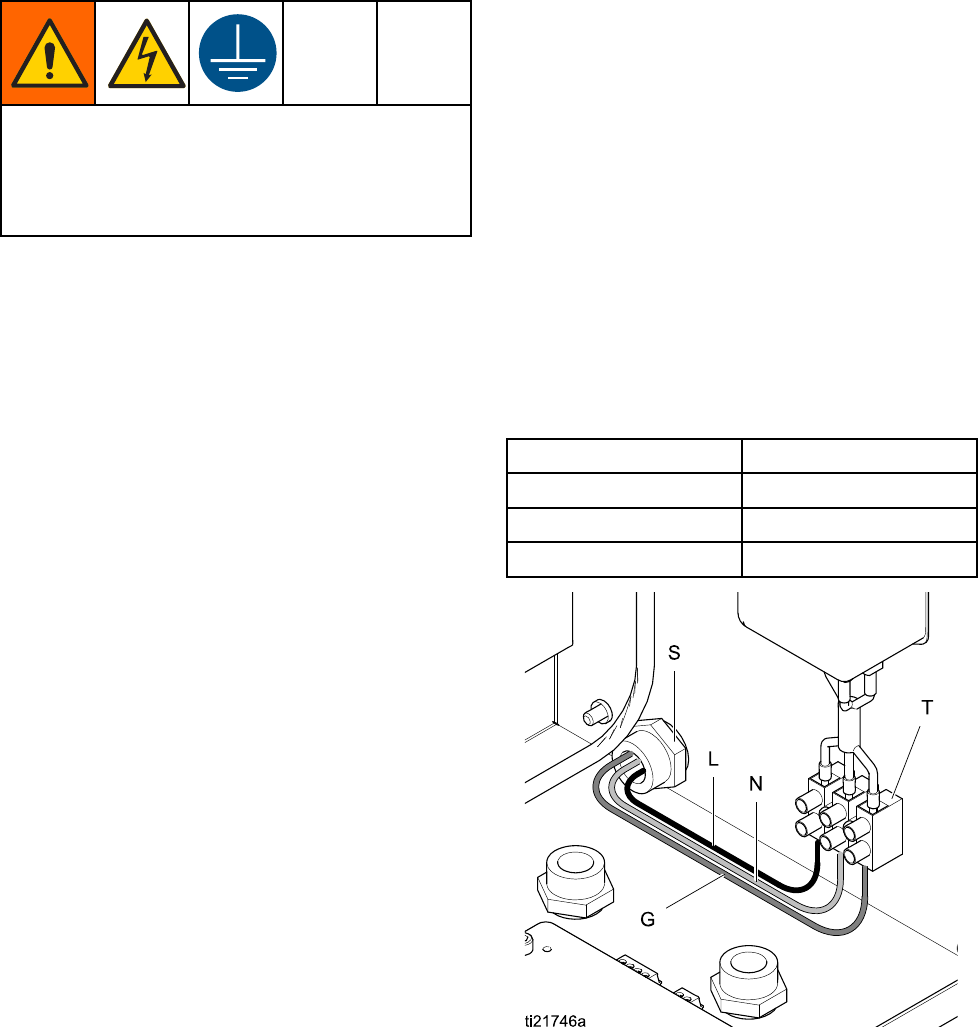
2. Thread the e
lectrical cord wires through the
strain reli
ef (S).
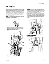
3. Connect the
wires (L, N, G) securely to the
correspon
ding terminals of the terminal block (T),
as shown.
4. Tighten th
e strain relief nut securely.
5. Close the
Control Box. Restore power.
6. Follow in
structions in Grounding, page 26.
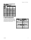
Wire Key
Wire Description
L Line Power
NNeutral
G Ground
Figure 14 Control Box Electrical Connection
332458B 25