


Install the Disp
lay Module
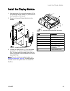
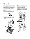
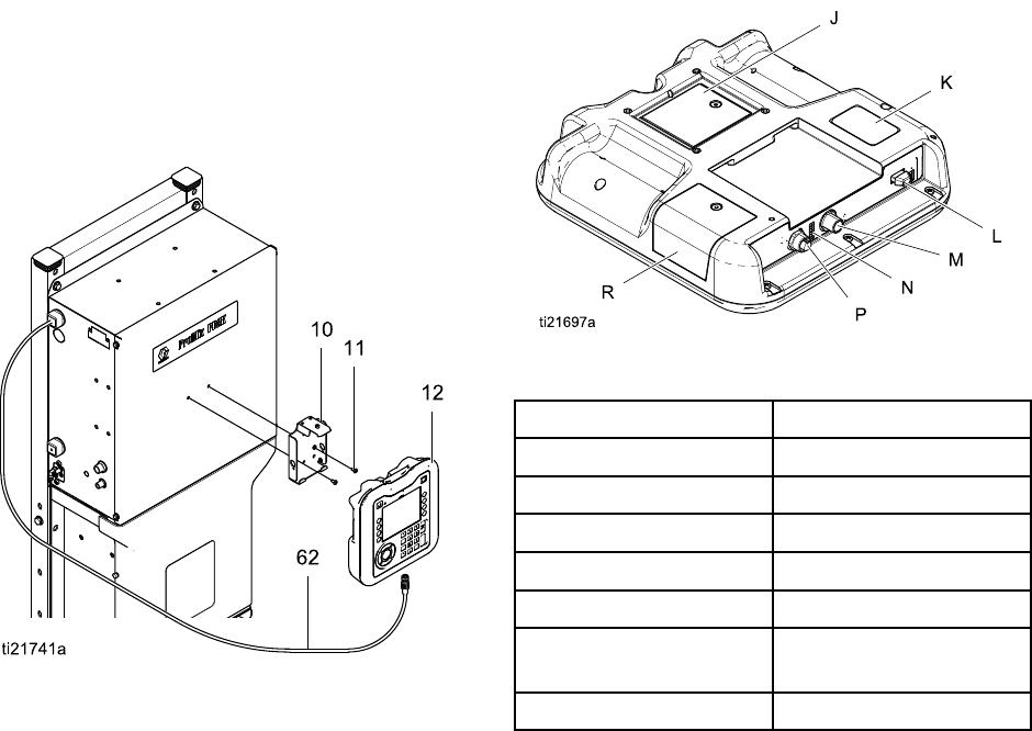
Install the Display Module
1. Use the screws
(11) to mount the bracket (10) for
the Advanced D
isplay Module (12) on the front of
the Control Bo
x or on the wall.
2. Snap the Adva
nced Display Module into the
bracket.
Figure
9 Install Display Module
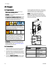
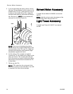
3. Connec
t one end of the 5 ft (1.5 m) CAN cable
(provi
ded) to the Advanced Display Module
(M). Th
e other end of the cable comes from the
facto
ry connected to the Enhanced Fluid Control
Modul
e(EFCM).
NOTE: For a list of alternate cable lengths, see
Electrical Schematics, page 29. The total length of
all cable used in the system must not exceed 150
ft (45 m).
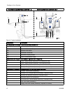
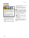
Figure 10 A
dvanced Display Module Connection
Ports
Item Descripti
on
J
Battery Cover
K Model Nu
mber
L
USB Drive Interface
M
CAN Cable Connection
N
ADM Sta
tus LEDs
P
Accessory Cable
Connection
R
Token Access Cover
332458B 19