


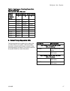
Configure Your Sy
stem
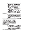
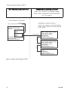
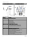
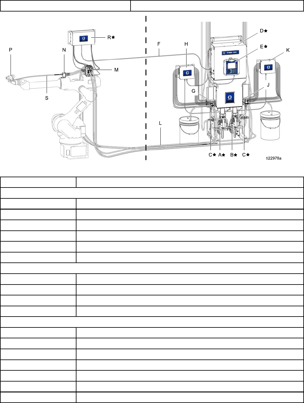
HAZARDOUS (CLASSIFIED) LOCATION NON-HAZARDOUS LOCATION ONLY
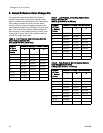
Figure 8 Typical Installation
Component
Description
★ Components A through F are included with the base unit.
A★
Materia
l A (Color) Pump
B★
Material B (Catalyst) Pump
C★ Solvent Flow Switch
D★
Elect
rical Control Box
E★ Advanced Display Module
F★
CAN C
ommunication Cable
Components G through K are included in optional color change kits.
G Color Change Valves (accessory, non-hazardous area)
H
Co
lor Change Module (accessory, non-hazardous area)
J
Catalyst Change Valves (accessory, non-hazardous area)
K
Catalyst Change Module (accessory, non-hazardous area)
C
omponents L through S are accessories and must be ordered separately.
L
Fluid/Air Hose Bundle (accessory)
M
Remote Color Change Manifold (accessory, hazardous area)
N
Remote Mix Manifold (accessory, hazardous area)
P
Automatic Spray Gun (accessory)
R
IS Remote Mix Control Module (accessory, hazardous area)
S Gun Fluid Hose (accessory)
T
Supply Line Drain Valves (accessory, required, not shown)
1
2
332458B