


Troubleshootin
g
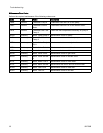
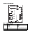
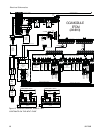
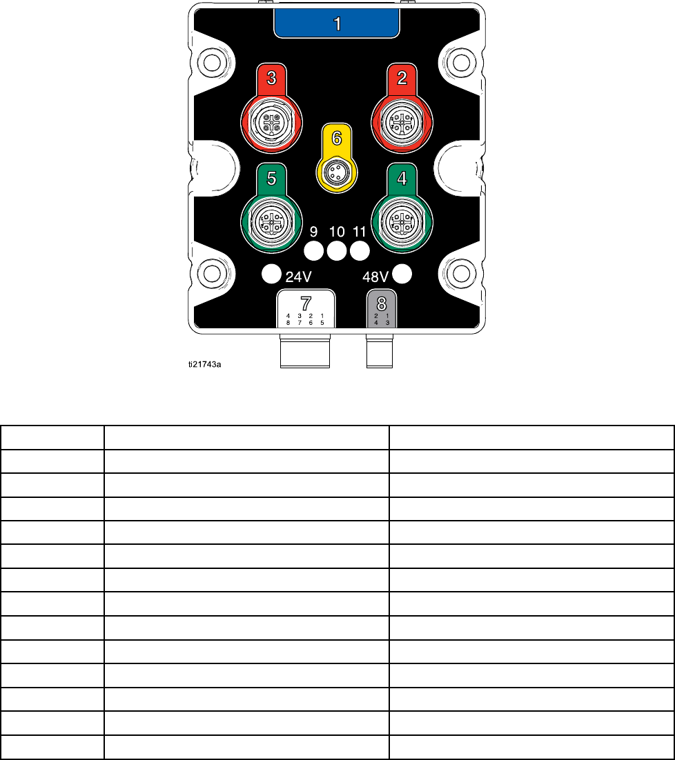
Pump Module Diagnostics
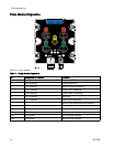
Figure 10 Pump Module
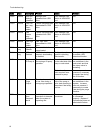
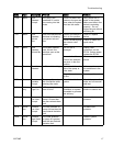
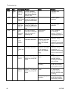
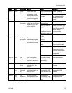
Table 4 . Pump Module Diagnostics
ID
Component or Indicator
Function
1 25 pin connector
Input from EFCM
2 5 pin connector Pump connection
3 5 pin connector Motor encoder connection
4 5 pin connector Pump Inlet Transducer
5
5 pin connector
Pump Outlet Transducer
6 4 pin connector Not used
7 8 pin connector
Dose Valve Solenoids
8 4 pin connector
48 Vdc Input Power and fan connection
9
LED (red) Pump Up Valve Output
10
LED (red) Pump Down Valve Output
11
LED (red)
Not used
24V
LED (green)
24 Vdc power supplied
48V
LED (green)
48 Vdc power supplied
2
4
332709B