


Repair
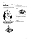
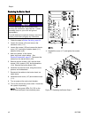
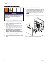
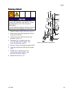
Replacing a Pump Control Module
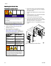
NOTICE
To avoid damaging the circuit boards when
servicing the control box, wear Part No. 112190
grounding strap on your wrist and ground
appropriately.
To avoid electrical component damage, remove all
system power before plugging any connectors.
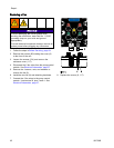
1. Follow the steps in Before Servicing, page 34.
2. Loosen the screws (124) and remove the
enclosure cover (117).
3. Note the position of the pump control module
cables. See Electrical Schematics, page 27.
Disconnect the cables from the pump control
module (132).
4. Remove the screws (143) and washers (177)
holding the pump control module to the
enclosure. Remove the pump control module.
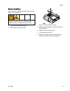
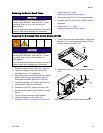
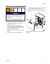
5. Instal
l the new pump control module, using the
screws
(143) and washers (177).
6. Reconnect the cables to the positions as noted
above.
7. Turn on power a
t the main circuit breaker.
8. Turn on the con
trol box power switch. Check that
the 48V green L
ED and the 24V green LED on
each of the pum
p control modules (132) are on.
NOTE: If the pumps do not work, recheck the
wiring.
9. Reinstall the cover (117) and tighten the screws
(124).
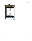
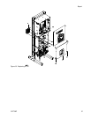
Figure 29 Replacing a Pump Control Module
4
4
332709B