Setup
333309E 17
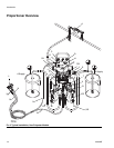
A and B Components
NOTE: Material suppliers can vary in how they refer to
plural component materials.
Be aware that when facing the manifold on the propor-
tioner:
• Component A is on the left side.
• Component B is on the right side.
For all machines:
• The A side is intended for polyols, resins, and
bases.
• If one of the materials being used is moisture-
sensitive, that material should always be in the B
side.
• The B side is intended for ISO, hardeners, and cata-
lysts.
NOTE: For machines with material volume ratios other
than 1:1, the higher volume side is typically at the A
side.
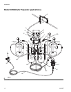
Polyester Model 24W609: This model is intended for
use with split-batch polyester applications. The A side
will contain polyester, resin, and the promoter. The B
side will contain polyester, resin, and the activator.
Checking the Mix Ratio
The pump must be operating in order to accurately
check the proportioning ratio of the pumps. The outlet
pressures at the pumps must be maintained at a mini-
mum level of 4 times that of the inlet pressures.
When the mix manifold is removed to check the mix
ratio, a flow restrictor will be needed to simulate the
pressure conditions during normal operation. The pre-
ferred flow restrictor is a small diameter, 1/16 in. ID, 1/2
in. (13 mm) long steel tube, coupled to the fluid supply
hoses. A needle-type flow control valve could also be
used. Contact your Graco distributor for assistance in
selecting the proper type of flow restrictor for your appli-
cation.
If the mixed fluid does not cure or harden properly,
check the ratio of part A to part B. To check the ratio:
1. Relieve the pressure, see page 19.
2. Flush the mixed fluid out of the mix manifold, dis-
pensing lines, and equipment.
3. Disconnect the fluid hoses from the mix manifold
inlet, taking note of which hose was connected to
which valve.
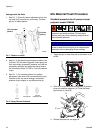
4. Place the hose ends into a waste container. Set two
graduated cylinders of the same size next to the
waste container. See F
IG. 5.
5. Set the air pressure to the proportioning pumps at
zero pressure. Open the air shut off valves to the
feed pumps and proportioning pump.
6. Turn up air pressure until fluids are flowing freely, at
exactly the same time, move the hoses over the cyl-
inders – part A hose over one cylinder and part B
hose over the other.
Cross-contamination can result in cured material in
fluid lines which could cause serious injury or damage
equipment. To prevent cross-contamination:
• Never interchange component A and component
B wetted parts.
• Never use solvent on one side if it has been con-
taminated from the other side.


