


Operation Basics
14 311321H
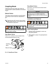
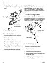
3. Insert coupling block mounting screw and
use 5/16 in. nut driver to tighten to gun
block.
FIG. 15: Install Coupling Block
Remove Coupling Block
1. Set safety stop to CLOSED (SERVICE).
2. Disconnect air hose.
3. Close both manual valves.
4. Remove coupling block mounting screw.
5. Separate coupling block from gun.
6. Wipe mating surfaces of gun block and
coupling block to remove residual chemical.
7. Cover exposed openings with grease.
Optional Configuration
Refer to page 42. If bottom-mount hose con-
nection is desired, alternate swivel fitting (2
and 3) with pipe plugs (1). Use pipe thread
sealant. Do not cross-over which side each fit-
ting is on.
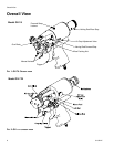
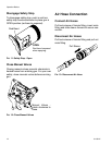
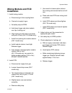
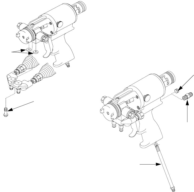
Air Inlet Configuration
There are two configurations for the air inlet. In
the standard configuration the air inlet is at the
base of the handle, and in the alternate config-
uration the air inlet is at the rear of the gun.
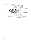
FIG. 16: Air Inlet Configuration
To change to alternate configuration,
1. Remove pipe nipple.
2. Remove pipe plug from rear of gun.
3. Install pipe plug in location previously occu-
pied by pipe nipple.
4. Install pipe nipple in location previously
occupied by pipe plug.
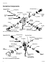
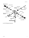
Coupling Block
Gaskets
Coupling Block
Mounting Screw
Pipe
Plug
Optional Pipe
Nipple
Pipe Nipple