


Repair
311321H 25
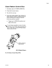
Replace End Cap and Air
Piston Assembly
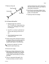
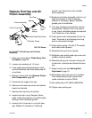
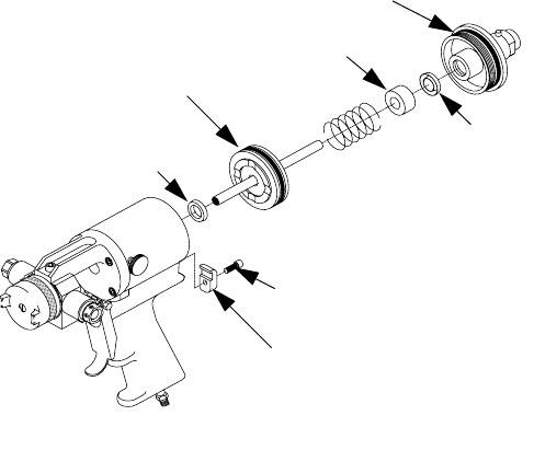
FIG. 25: GX-7 DI End Cap and Air Piston
Assembly
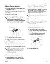
1. Clean gun according to Clean Spray Gun
Procedure, page 20.
2. Loosen rear packing nut 1-2 turns.
3. Push safety stop partially forward, rotate
counterclockwise, and slide safety stop off
air cylinder.
4. Remove valving rod. See Remove Center-
line Components, page 22.
5. Disconnect air supply from gun.
6. Remove rear head cap screw and cylinder
clamp from handle.
7. Remove end cap from air cylinder.
8. Inspect end cap o-ring. Replace if dam-
aged. Install new end cap o-ring after lightly
coating it with Lubriplate grease.
9. Inspect rear U-cup seal or o-ring for dam-
age. Replace if necessary. If removed,
ensure “cup” faces front of air cylinder
when replacing.
10.By hand, pull piston assembly out of air cyl-
inder and inspect o-ring for damage.
Replace if necessary. Apply Lubriplate
grease prior to installation.
11.If air was escaping around piston rod dur-
ing operation, replace front u-cup seal or
o-ring. Apply Lubriplate grease and ensure
“cup” faces rear of air cylinder.
12.Insert piston and rod assembly into air cyl-
inder. Take care to not damage front cup
seal as rod passes through.
13.Insert piston spring. (For GX-7 DI models,
also insert piston spacer.)
14.Reinstall end cap into air cylinder.
15.Retighten rear socket head cap screw and
cylinder clamp to handle.
16.Reinstall valving rod. Connect valving rod
to draw bar. Lubricate and thread into end
cap.
17.Adjust valving rod; see Valving Rod
Adjustment, page 16.
18.Slide safety stop onto rear of air cylinder.
Push safety stop partially forward and
rotate clockwise to set to OPEN.
19.Set safety stop to CLOSED (SERVICE).
20.Tighten rear packing nut.
GX-7 DI Shown
End Cap
Spacer
Rear
U-Cup
Seal
Piston
Spring
Piston Assembly
Front U-Cup Seal
Socket Head Cap Screw
Cylinder Clamp