


Models
2 311321H
Contents
Models . . . . . . . . . . . . . . . . . . . . . . . . . . . . . . . . . . . 2
Warnings . . . . . . . . . . . . . . . . . . . . . . . . . . . . . . . . . 3
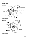
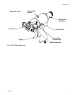
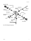
Overall View . . . . . . . . . . . . . . . . . . . . . . . . . . . . . . . 6
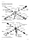
Centerline Components . . . . . . . . . . . . . . . . . . . 8
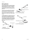
Mixing Module . . . . . . . . . . . . . . . . . . . . . . . . . . 10
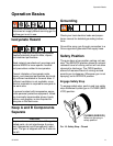
Operation Basics . . . . . . . . . . . . . . . . . . . . . . . . . . 11
Isocyanate Hazard . . . . . . . . . . . . . . . . . . . . . . 11
Keep A and B Components Separate . . . . . . . . 11
Grounding . . . . . . . . . . . . . . . . . . . . . . . . . . . . . 11
Safety Position . . . . . . . . . . . . . . . . . . . . . . . . . 11
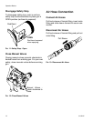
Air Hose Connection . . . . . . . . . . . . . . . . . . . . . 12
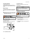
Coupling Block . . . . . . . . . . . . . . . . . . . . . . . . . 13
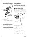
Air Inlet Configuration . . . . . . . . . . . . . . . . . . . . 14
Mixing Module and PCD Installation . . . . . . . . . 15
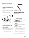
Valving Rod Adjustment . . . . . . . . . . . . . . . . . . 16
Valving Rod Adjustment . . . . . . . . . . . . . . . . . . 16
Initial Set Up . . . . . . . . . . . . . . . . . . . . . . . . . . . 17
Daily Start-up . . . . . . . . . . . . . . . . . . . . . . . . . . 18
Daily Shutdown . . . . . . . . . . . . . . . . . . . . . . . . . 18
Pressure Relief Procedure . . . . . . . . . . . . . . . . . . 19
Maintenance . . . . . . . . . . . . . . . . . . . . . . . . . . . . . . 20
Gun Service Kits . . . . . . . . . . . . . . . . . . . . . . . . 20
Clean Spray Gun Procedure . . . . . . . . . . . . . . . 20
Flush Gun . . . . . . . . . . . . . . . . . . . . . . . . . . . . . 21
Repair . . . . . . . . . . . . . . . . . . . . . . . . . . . . . . . . . . . 22
Service Screen Screw . . . . . . . . . . . . . . . . . . . . 22
Remove Centerline Components . . . . . . . . . . . 22
Install Centerline Components . . . . . . . . . . . . . 24
Replace End Cap and Air Piston Assembly . . . 25
Replace Trigger Valve O-Rings . . . . . . . . . . . . . 26
Clean Mixing Module . . . . . . . . . . . . . . . . . . . . . 27
Install Mixing Module . . . . . . . . . . . . . . . . . . . . . 28
Clean Pattern Control Disc . . . . . . . . . . . . . . . . 29
Parts . . . . . . . . . . . . . . . . . . . . . . . . . . . . . . . . . . . . 30
GX-7A Model Final Assembly . . . . . . . . . . . . . . 30
GX-7 DI Model Final Assembly (295541) . . . . . 32
GX-7 400 Model Final Assembly (295540) . . . . 34
GX-7A Model Handle Assembly (295810) . . . . . 36
GX-7 DI Model Handle Assembly (295809) . . . 38
GX-7 400 Model Handle Assembly (295799) . . 40
Coupling Block Assembly (295383) . . . . . . . . . . 42
Specifications . . . . . . . . . . . . . . . . . . . . . . . . . . . . . 43
GX-7A Mix Module Kit . . . . . . . . . . . . . . . . . . . . 43
Set-Up Chart for GX-7A Model . . . . . . . . . . . . . 44
GX-7 400 Mix Module Kit . . . . . . . . . . . . . . . . . . 45
Set-up Chart for GX-7 400 Model . . . . . . . . . . . 46
GX-7 DI Model Specifications . . . . . . . . . . . . . . 47
Tip Kits . . . . . . . . . . . . . . . . . . . . . . . . . . . . . . . . 48
Tool Kits . . . . . . . . . . . . . . . . . . . . . . . . . . . . . . . 48
Technical Data . . . . . . . . . . . . . . . . . . . . . . . . . . . . 49
Graco Standard Warranty . . . . . . . . . . . . . . . . . . . 50
Graco Information . . . . . . . . . . . . . . . . . . . . . . . . . 50
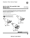
Models
.
Part No. Description
Includes:
Mix Module Tip
295540 GX-7 400 296859 (451)
296853 (212)
295541 GX-7 DI - 4/213 296901 (4)
296706 (213)
295542 GX-7A - 1/90 296909 (1)
296712 (90)
295543 GX-7A - 10/210 296906 (10)
296704 (210)
295544 GX-7A - 3/70 296226 (3)
296710 (70)
295545 GX-7A - 5/70 296923 (5)
296710 (70)