


Operation Basics
16 311321H
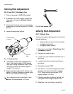
Valving Rod Adjustment
GX-7A and GX-7 400 Models Only
1. Push in rear stop to SERVICE position.
2. If attached, turn both manual valves fully
clockwise to close (see Manual Valves,
page 13).
3. Connect air line from gun to air source to
pressurize air cylinder forward to CLOSED
position.
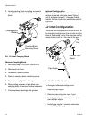
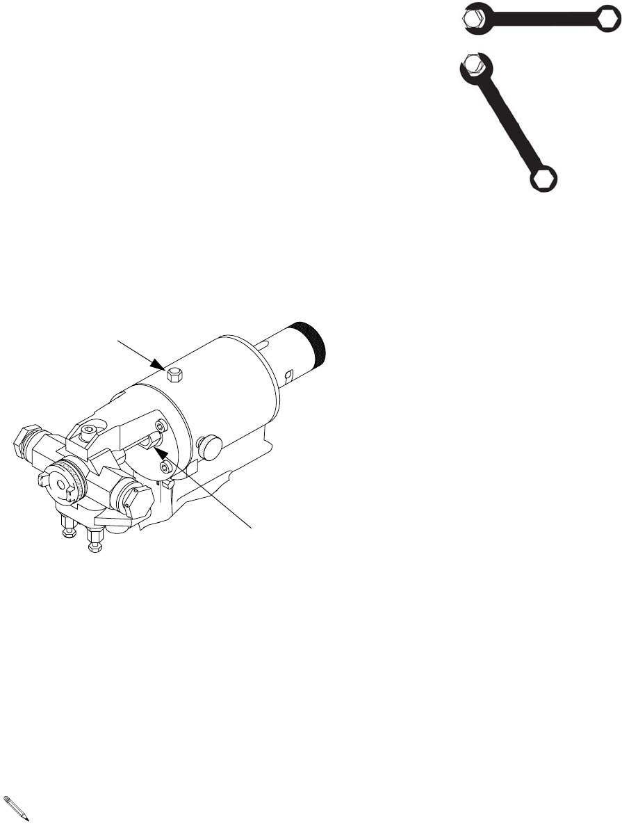
4. Loosen forward stop locknut.
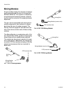
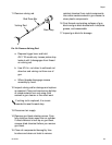
FIG. 17: Forward Stop
5. Completely loosen (full CCW) forward
stop. Then slowly tighten (CW) forward
stop until a snug resistance is felt. From
this point, reverse and loosen approxi-
mately 1/16 of a turn.
6. Tighten forward stop locknut. Do not over-
tighten. If locknut bottoms out before resis-
tance is felt, replace friction plug.
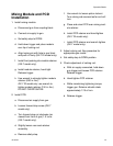
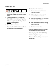
FIG. 18: One Wrench Flat
Valving Rod Adjustment
GX-7 DI Model Only
Valving rod requires adjustment in only the fol-
lowing instances:
• disassembly and service of air cylinder
• changing valving rod
• changing mixing module
1. Clean gun according to Clean Spray Gun
Procedure, page 20.
2. Connect air supply to gun.
3. Loosen rear seal retainer assembly one or
two turns.
4. Loosen locknut from valving rod three or
four turns.
5. Set safety stop to OPEN.
6. Use 5/16 in. nut driver through rear of gun
to thread valving rod forward to engage
PCD. When valving rod contacts PCD
tighten another 1/10 turn.
7. Carefully maintain position of valving rod
and tighten locknut against piston rod.
8. Retighten rear seal retainer assembly.
As a reference point, movement of one
wrench flat corresponds to 1/6 turn.
Forward
Stop
Forward Stop
Locknut