-2-
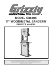
G0640X 17" Wood/Metal Bandsaw
INTRODUCTION
Foreword
We are proud to offer the Model G0640X 17"
Wood/Metal Bandsaw. This machine is part of a
growing Grizzly family of fine machinery. When
used according to the guidelines set forth in this
manual, you can expect years of trouble-free,
enjoyable operation and proof of Grizzly’s com-
mitment to customer satisfaction.
The specifications, drawings, and photographs
illustrated in this manual represent the
Model
G0640X as supplied when the manual was pre-
pared. However, owing to Grizzly’s policy of con
-
tinuous improvement, changes may be made at
any time with no obligation on the part of Grizzly.
For your convenience, we always keep current
Grizzly manuals available on our website at
www.grizzly.com. Any updates to your machine
will be reflected in these manuals as soon as they
are complete.
If you have any comments regarding this manual,
please write to us at the address below:
Grizzly Industrial, Inc.
C
/O Technical Documentation Manager
P.O. Box 2069
Bellingham, WA 98227-2069
Email: manuals@grizzly.com
We stand behind our machines. If you have any
service questions or parts requests, please call or
write us at the location listed below.
Grizzly Industrial, Inc.
1203 Lycoming Mall Circle
Muncy, PA 17756
Phone: (570) 546-9663
Fax: (800) 438-5901
E-Mail: techsupport@grizzly.com
Web Site: http://www.grizzly.com
Contact Info
The bandsaw is one of the most versatile cutting
tools in the shop and is capable of the following
cuts:
• Miters and angles
• Compound Angles
• Resaw Cuts
• Rip and Crosscuts
• Curves and Circles
• Stacked Cuts for Duplicate Parts
The blade is a flexible steel band with teeth on
one edge that fits around two aligned wheels with
slightly crowned rubber tires, which help the blade
track in the center of the wheels during opera
-
tion.
One wheel stays in a fixed position and is driven
by a motor. The other wheel spins freely and
adjusts toward or away from the fixed wheel,
which controls the tension of the installed blade.
This wheel usually also features a tracking control
that tilts the wheel forward or backward to ensure
the blade rides in the center of the wheel. The
rotation of both wheels pulls the blade downward
toward the table.
When a workpiece is pushed against the mov
-
ing blade, the downward force of the blade teeth
scrape across the workpiece and, in effect, cut
it. Blade guides on both sides of the cutting area
keep the blade from flexing or being pushed off
the wheels from the horizontal pressure of the
workpiece while cutting.
Since the purpose of the blade guides is to
provide support while cutting, they should be
as close as possible to the blade; however, the
blade guides should only touch the blade while a
workpiece is being cut, or the constant friction will
reduce the life of the blade. Also the upper blade
guide assembly should be adjusted as close as
possible to the workpiece to provide maximum
support and cover any unused area of the blade
with the blade guard.
Functional Overview


