-42-
G0640X 17" Wood/Metal Bandsaw
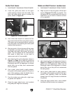
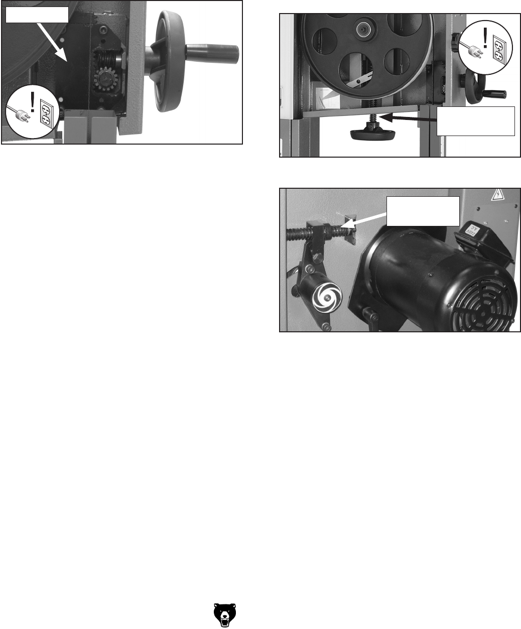
Guide Post Gears
1. DISCONNECT BANDSAW FROM POWER!
2. Lower the guide post down so the upper
guide bearings almost touch the table, then
open the upper wheel cover to access the
gears, shown in
Figure 56.
3. Use a 6mm hex wrench to remove the four
cap screws that hold the cover plate in place.
(The gears can be greased without removing
the cover plate, but removing the cover plate
makes cleaning easier.)
4. Wipe as much of the old grease off the gears
as possible, and also wipe off the rack (the
long plate with teeth that contact the pinion
gear). The old grease will be contaminated
with wood or metal dust, so you want to
remove as much of it as possible.
5. Use mineral spirits or the degreaser shown in
Figure 4 on Page 12 to clean any remaining
grease from the gears and rack. Make sure to
thoroughly wipe off the degreaser or mineral
spirits after use so they won't contaminate
the new grease.
6. Use a small, clean brush to apply automo-
tive-grade multi-purpose grease to the pinion
gear. After applying, rotate the handle two or
three times to distribute the grease.
7. Coat the inside cover plate with a light layer
of grease and replace it.
8. Close the upper wheel cover, and re-adjust
the guide post height as necessary.
Blade and Belt Tension Leadscrews
1. DISCONNECT BANDSAW FROM POWER!
2. Wipe as much of the old grease off the lead-
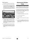
screws (
Figures 57 & 58) as possible. The
old grease will be contaminated with wood or
metal dust, so you want to remove as much
of it as possible.
3. Use mineral spirits or the degreaser shown in
Figure 4 on Page 12 to clean any remaining
grease from the leadscrews. Make sure to
thoroughly wipe off the degreaser or mineral
spirits after use so they will not contaminate
the new grease.
4. Use a small, clean brush to apply automo-
tive-grade multi-purpose grease to the lead
-
screws. After applying, rotate the handles
through their full range of motion to distribute
the grease.
5. Close the upper wheel cover, and re-adjust
the blade and belt tension as necessary.
Figure 58. Belt tension crank leadscrew.
Belt Tension
Lead Screw
Figure 56. Guide post gears.
Cover Plate
Figure 57. Blade tension leadscrew.
Blade Tension
Lead Screw


