


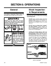

-18-
G0526 6" Jointer
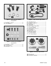
Components and Hardware Needed: Qty
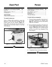
Dust Port......................................................1
Phillips Screws
1
⁄4"-20 x
1
⁄2" ..........................4
Flat Washers
1
⁄
4" ..........................................4
Tools Needed:
Phillips Head Screwdriver............................1
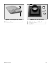
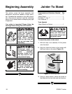
To install the dust port:
Using a Phillips head screwdriver, secure the
dust port to the dust chute opening with the
Phillips screws and flat washers (Figure 15).
Note—Make sure the dust port hose hook-up is
positioned over the lower portion of the dust
chute opening.
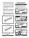
Figure 15. Correctly installed dust port.
Figure 16. Correctly installed fence assembly.
Components and Hardware Needed: Qty
Fence Assembly ..........................................1
Lock Handle
1
⁄2"-12 x 1
1
⁄4" ............................1
Special Nut
1
⁄2
"-12 ........................................1
Flat Washer
1
⁄2
" ............................................1
Tilt Lever W/Knob ........................................1
To attach the fence assembly:
1. Place the fence assembly on the jointer as it
was before removing it for cleaning (see
page 15), making sure the key and keyways
align with one another.
2. Secure the fence assembly to the jointer with
the lock handle, the flat washer, and the spe-
cial nut (Figure 16). Note—Make sure the
flanges on the special nut protrude upward
and into the slot on the underside of the
fence support.
FenceDust Port
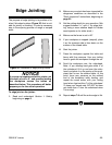
3. Thread the tilt lever into the fence casting.
Tilt Lever
Threading
Location