


-34-
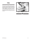
G0524 Rip Saw
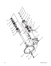
Laser Guide with Arm - H5749
Improve rip cutting accuracy, work more efficient
-
ly, and increase yields with the optional Grizzly
H5749 Laser Guide. This bolt-on accessory is
perfect for production shop looking to make the
most of their Grizzly G0524 Rip Saw.
Inventory Qty
• Steel Arm .....................................................1
• Laser Bracket ..............................................1
• Laser Clamp ................................................1
• Laser ............................................................1
• Power Box ...................................................1
• Cap Screws M8-1.25 x 25 ...........................4
• Flat Washers 8mm ......................................4
• Lock Washers 8mm .....................................4
• Cap Screws M6-1 x 16 ................................2
• Flat Washers 6mm ......................................2
• Cap Screws M6-1 x 35 ................................2
• Phillips Head Screws M5-.8 x 8 ..................2
To install the laser guide on the Model G0524
Rip Saw:
1. Disconnect the Model G0524 Rip Saw
from the power source!
2. Attach the steel arm to the head casting
with the (4) M8-1.25 x 25 cap screws, (4)
8mm flat washers, and (4) M8 lock wash
-
ers. Note—The mounting location and drill
pattern for the steel arm are shown on
page
46. The holes must be drilled and tapped to
accept M8-1.25 threads.
3. Mount the laser bracket to the top of the steel
arm with the (2) M6-1 x 16 cap screws and
(2) 6mm flat washers.
4. Place the laser clamp around the laser and
secure the assembly to the laser bracket with
the (2) M6-1 x 35 cap screws.
5. Attach the black power box to the rip saw
with the (2) M5-8 x 8 Phillips head screws.
Note—Make sure the loose end of the green
ground wire is secured between the head of
the Phillips screw and the black power box.
6. Route the power wires from the power box
through the side of the saw base and into the
electrical panel compartment.
7. Connect the R1 and T1 power wires to their
respective R1 and T1 locations on the main
terminal at the electrical panel.
8. Feed the laser power wire through the access
holes on the steel arm, and plug the power
wire into the back of the power box.
9. Cut a board, turn the saw OFF, place the
board against the fence, and finally, adjust
the laser beam along the freshly cut edge
.
DO NOT look into the end of the laser.
Serious eye damage will occur.
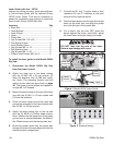
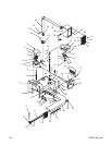
Figure 1. Model H5749 Laser Guide.
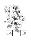
Figure 2. Electrical wiring.
Laser
Power Box
Laser
Bracket
Laser
Clamp
Steel Arm
Placement