


-20- G0555 14" Ultimate Bandsaw
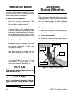
Tensioning Blade
A properly tensioned blade is essential for mak-
ing accurate cuts and is a prerequisite before
making many bandsaw adjustments.
To tension the bandsaw blade:
1. Make sure you have performed the “Test
Run” instructions on the previous page and
that the blade is tracking properly.
2. With the blade tension lever in the down
(engaged) position, adjust the blade tension
so that the mark on the blade tension scale
matches the size of blade that is installed on
the bandsaw. Because each blade is differ-
ent and all blades stretch, this scale can only
be considered as a general guide.
3. Turn the bandsaw ON.
4. Release the tension one quarter of a turn at
a time. Do this very slowly. When you see
the bandsaw blade start to flutter, stop
decreasing the tension.
5. Now, slowly increase the tension until the
blade stops fluttering, then tighten the ten-
sion one more quarter of a turn.
6. Look at what the tension gauge reads and
use that as a guide for tensioning that blade
in the future. However, do not rely on this
measurement for long periods of time
because the blade will stretch with use.
NOTICE
All bandsaw blades will stretch. To reduce
this stretching, remove the tension from the
blade when not in use.
NOTICE
After blade tension and tracking are set cor-
rectly, properly adjust the upper and lower
support bearings and guide-block assem-
blies into position before cutting operations.
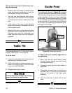
Adjusting
Support Bearings
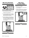
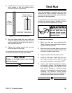
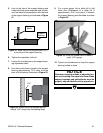
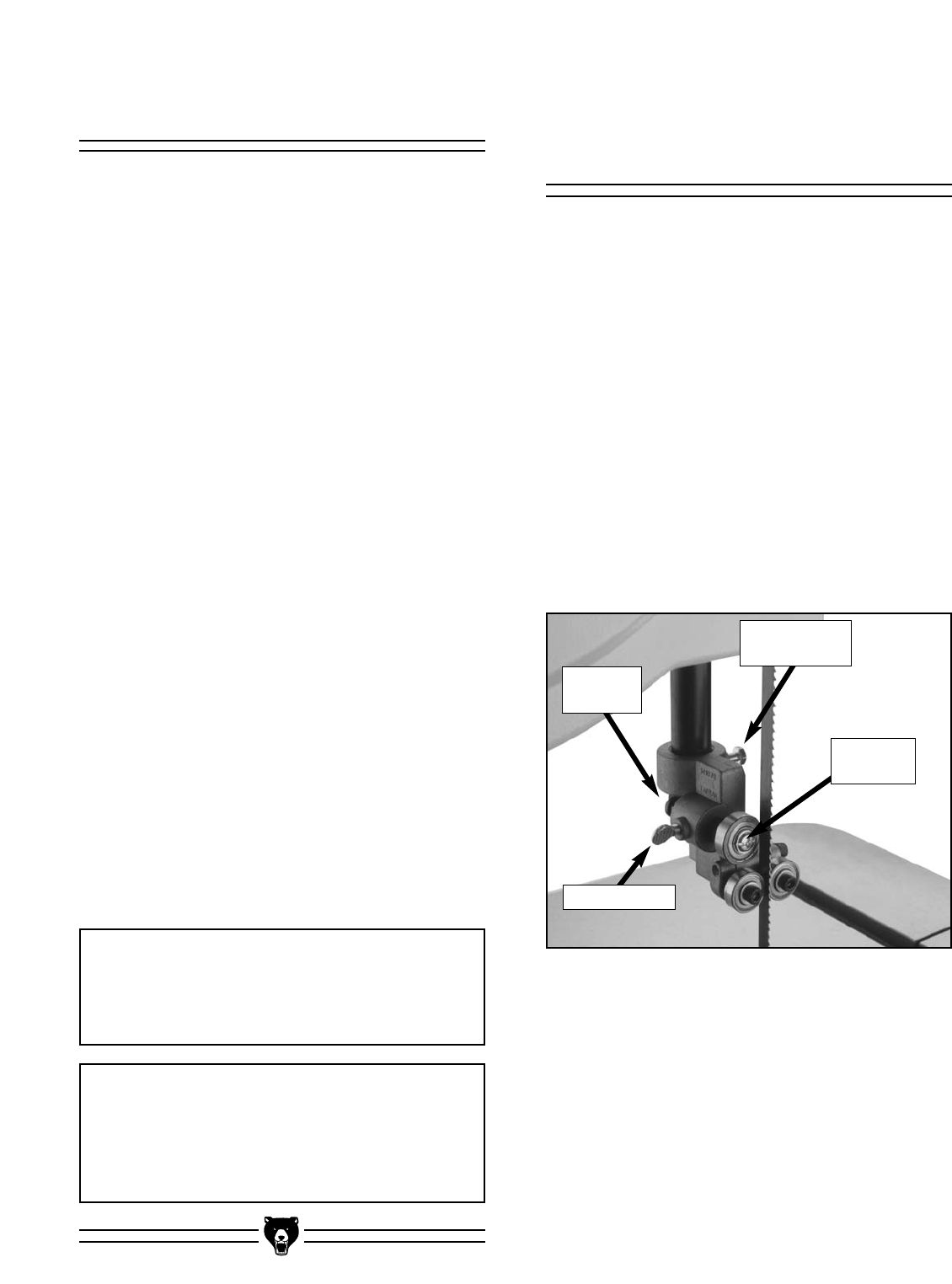
Figure 20. Support bearing controls.
The support bearings are positioned behind the
blade and support the back of the blade during
cutting operations. Proper adjustment of the sup-
port bearings is an important part of making accu-
rate cuts and also keeps the blade teeth from
coming in contact with the guide bearings while
cutting.
To adjust the support bearings:
1. Make sure that the blade is tracking properly
and that it is correctly tensioned.
2. Unplug the bandsaw!
3. Familiarize yourself with the support bearing
controls shown in Figure 20.
4. Loosen the assembly lock bolt.
Thumbscrew
Knurled
Knob
Assembly
Lock Bolt
Support
Bearing