-26-
G0555X 14" Extreme Series Bandsaw
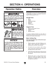
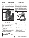
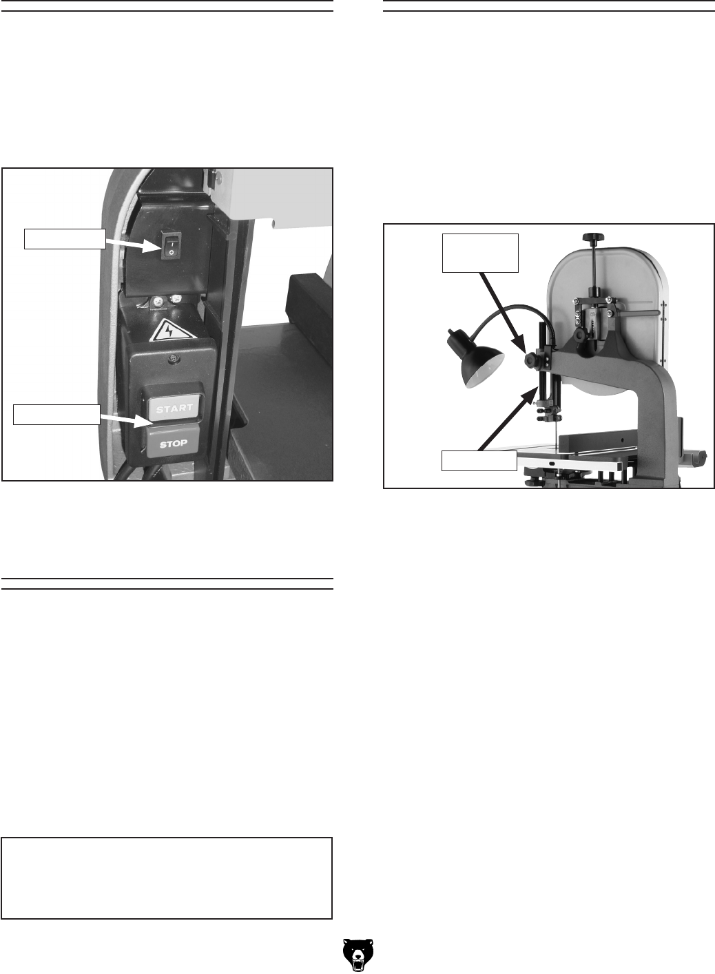
The motor switch is shown in Figure 27 and is
clearly marked for starting/stopping the machine
.
The light switch powers the lamp independently
from the motor switch. ALWAYS turn this switch
OFF (the "0" position) to cut power to the lamp
BEFORE changing the light bulb.
Motor & Light Switch
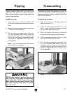
The bandsaw table tilts 10˚ left and 45˚ right to
provide a wide range of cutting options.
To tilt the table:
1. Loosen the two table-trunnion knobs under-
neath the table.
2. Tilt the table to the desired angle. (Refer to
the angle gauge on the front table trunnion.)
3. Retighten both table-tunnion knobs.
NOTICE
When tilting the table to the left, it is
necessary to remove the positive stop.
Table Tilt
To adjust the blade guide assembly on the
guide post (the bandsaw must be turned
OFF):
1. Make sure that the blade tension, blade
tracking, support bearing and blade guides
are adjusted correctly.
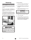
2. Loosen the guide post lock knob shown in
Figure 28.
3. Raise/lower the guide post so the bottom of
the blade guide assembly is less than 1" from
the top of the workpiece.
4. Lock the guide post with the lock knob.
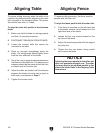
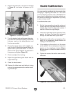
The guide post (shown in Figure 28) connects
the upper blade guide assembly to the bandsaw.
The guidepost allows the blade guide assembly to
move up or down to be as close to the workpiece
as possible. In order to cut accurately and safely,
the bottom of the blade guide assembly must be
no more than 1" from the workpiece at all times—
this positioning provides the greatest support to
the blade and minimizes operator exposure to the
blade.
Figure 28. Guide post controls.
Guide Post
Guide Post
Lock Knob
Guide Post
Figure 27. Motor & light switch.
Light Switch
Motor Switch


