


G0633/G0634 Jointer/Planer Combo Machine
-23-
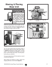
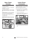
Table Movement: Loosen the cap screws on the
infeed handgrip and outfeed table adjustment
knob before moving the infeed and outfeed tables
(Figure 19). Use an adjustable wrench to turn the
outfeed adjustment knob.
Figure 19. Table control locations.
Outfeed Table
Adj. Knob
Infeed
Handgrip
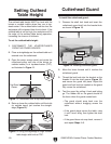
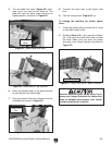
Fence Tilting: The tilt lock (Figure 20) secures
the fence at any position in the available range.
Fence stops set the fence at 90° or 45° outward.
The tilt lock must be tightened before cutting. See
Page 47
for more detail on adjusting the fence
stops.
Fence Movement: The fence lock keeps the
fence in position (Figure 20). To move the fence,
loosen the lock and turn the fence adjustment
knob to move it as needed.
Figure 20. Fence lock location.
Fence Adj.
Knob
Fence
Lock
Tilt
Lock
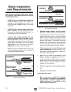
Figure 21. Fence flush with table at 45°.
To move the fence to 45° outward, loosen the tilt
lock and fence height knobs, move the fence flush
against the table (see Figure
21), and tighten the
height knobs and tilt lock. Verify the angle with a
45
° square. To return the fence to the 90° posi-
tion, loosen the tilt lock and height knobs, raise
the fence to 90°, and tighten the height knobs and
tilt lock. Check the fence angle with a 90
° square,
and make sure the fence and table are flush.
Fence Height Knobs
Cap Screw
Cap
Screw