


G0633/G0634 Jointer/Planer Combo Machine
-35-
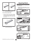
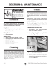
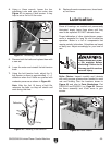
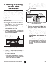
4. Using a 14mm wrench, loosen the four
adjustment nuts and raise the motor (see
Figure 47) to remove V-belt tension. It may
help to use a 2x4 to lift the motor.
8. Replace the motor access cover, fence brack-
et, and fence.
5. Remove both the belts and replace them with
a new set.
6. Lower the motor and reinstall the belt tension
knob.
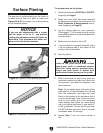
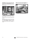
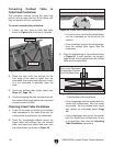
7. Using the belt tension knob, adjust the V-
belt tension so there is approximately
1
⁄4"–
1
⁄2"
deflection when the V-belts are pushed with
moderate pressure as shown in
Figure 48.
Note: After the first 16 hours of belt life,
retension the belts, as they will stretch and
seat during this time.
Figure 47. Removing V-belt tension.
Figure 48. Checking V-belt tension.
Adjustment
Nuts
Since all bearings are sealed and permanently
lubricated, simply leave them alone until they
need to be replaced. DO NOT lubricate them.
Proper lubrication of other jointer/planer compo
-
nents is essential for long life and trouble-free
operation. Below is a list of components that
require periodic lubrication. Schedules are based
on daily use. Adjust accordingly for your level of
use.
Lubrication
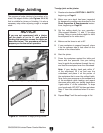
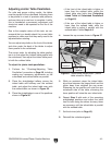
Roller Chains: Inspect monthly and lubricate
with multi-purpose grease when needed to avoid
rust and binding. See the locations shown in
Figure 49, and refer to Parts Breakdown, Part
P0633310 and P0633311 on
Page 60. Remove
the fence assembly and V-belt cover to gain
access.
Figure 49. Roller chains.
Always disconnect power
to the machine before
lubricating! Failure to do
this may result in serious
personal injury.
1
⁄4"–
1
⁄2"