


G0633/G0634 Jointer/Planer Combo Machine
-47-
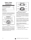
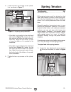
— If the pulleys are aligned, then no adjust-
ments are necessary.
— If the pulleys are NOT aligned, perform
Steps 3 &
4.
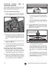
3. Remove the V-belts (see Page 34), loosen
the set screws on the end of the cutterhead
pulley, and align the
cutterhead pulley with the
motor pulley
.
4. Tighten the set screws, replace the V-belts,
and repeat Step 2.
5. Reinstall the V-belt cover, fence bracket and
fence assembly.
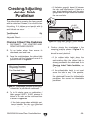
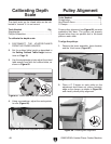
Figure 69. Pulleys properly aligned. V-belts are
parallel and coplaner.
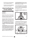
The fence stops simplify the task of adjusting the
fence to 45˚ and 90˚.
Tools Needed Qty
45° Square ........................................................
1
90° Square ........................................................
1
Sliding Bevel ......................................................
1
Wrench 10mm ...................................................
1
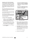
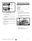
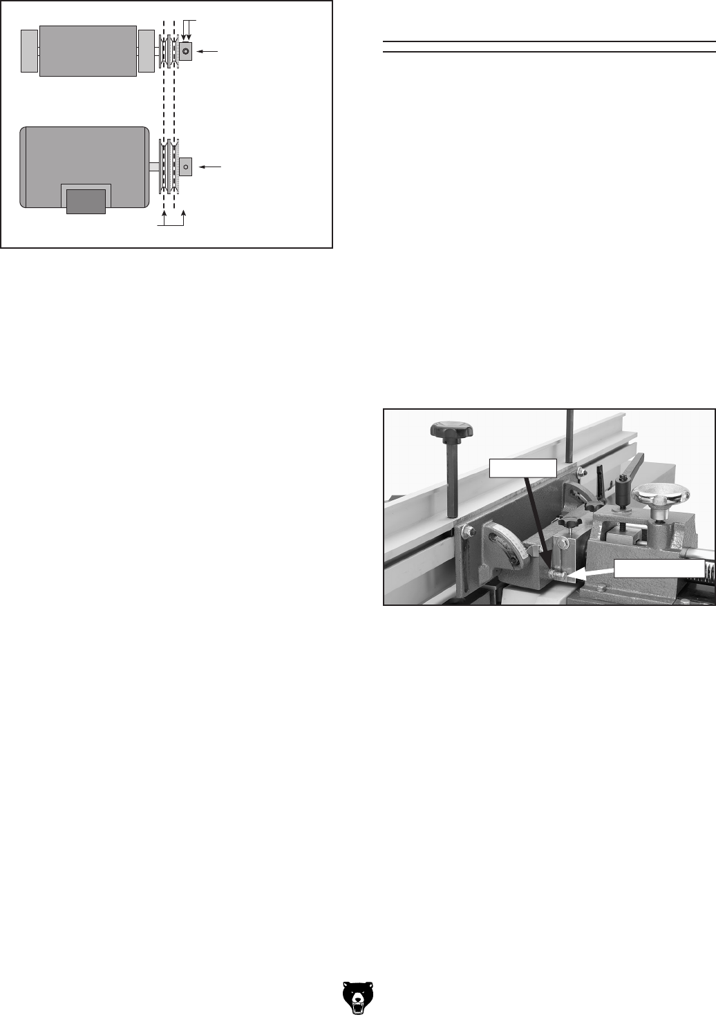
To set the 90˚ fence stop:
1. Loosen the lock nut on the 90° fence stop bolt
shown in
Figure 70, and loosen the fence tilt
lock.
2. Place a 90° square against the table and
fence, and adust the stop bolt
, so the fence
is set exactly at 90°
.
Setting Fence Stops
3. Tighten the lock nut.
4. Adjust the indicator (if necessary) to 0° to
calibrate the fence tilt scale.
Figure 70. Adjusting fence to 90˚.
Lock Nut
90˚Stop Bolt