


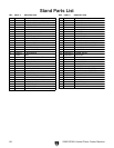
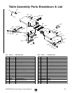
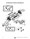
G0633/G0634 Jointer/Planer Combo Machine
-51-
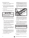
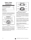
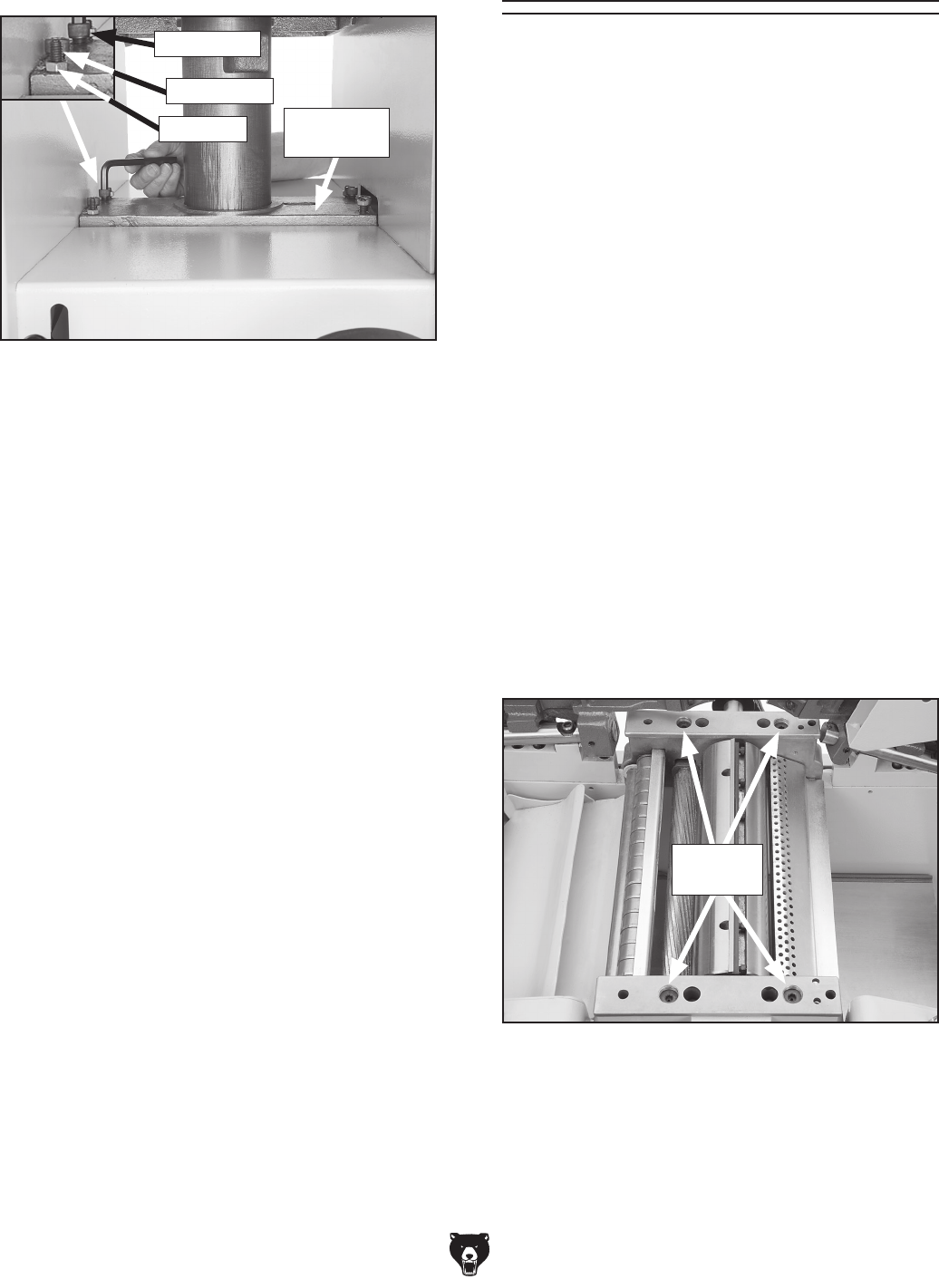
— If the table is not parallel to the cutterhead
side-to-side (Figure 75), loosen the two
lock nuts on the right or left side of the cyl
-
inder liner. Adjust the set screws to raise
or lower the table so it is parallel to the
cutterhead.
— If the table is not parallel to the cutterhead
front-to-back (
Figure 76), loosen the two
lock nuts at the front or back of the cylinder
liner. Adjust the set screws to raise or lower
the front or back of the table so it is parallel
to the cutterhead.
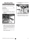
4. Tighten the four cap screws on the cylinder
liner.
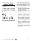
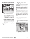
Spring Tension
Tools Needed: Qty
Hex Wrench
6mm .............................................. 1
Roller spring tension must be adjusted so that
feed roller pressure is uniform. Roller spring ten
-
sion will vary, depending on the type of wood you
plane. This is usually determined from trial-and-
error.
Generally speaking, less spring tension is more
forgiving on workpieces. Therefore, if you primar
-
ily plane milled lumber with relatively consistent
surfaces, you can get away with having less
spring tension. Likewise, if you primarily plane
rough lumber with inconsistent surface heights,
more spring tension is a must to keep the
workpiece feeding through the planer without
stopping.
If workpieces regularly stop feeding during opera
-
tion, it may be a sign of weak spring tension.
To adjust feed roller spring tension:
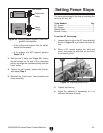
1. Locate the four adjustment screws located
on the top of the planer, as shown in
Figure
78.
3. Loosen the four cap screws on the cylinder
liner, as shown in
Figure 77.
Figure 77. Adjusting table parallelism.
Cylinder
Liner
Figure 78. Spring tension screws.
Tension
Screws
Lock Nut
Set Screw
Cap Screw