


-29-
G0668 20" Vertical Metal-Cutting Bandsaw
4. Loosen the welding clamps by pulling the
lock levers down.
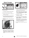
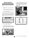
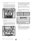
5. Position the back of one blade end evenly
against the back of the welding clamp so that
the end is midway between the two clamps,
then rotate that lock lever all the way up to
hold the blade end in place (see
Figure 29).
Figure 29. Blade end properly position in
welding clamp and locked in place.
Lock Lever
Welding
Clamp
Blade
End
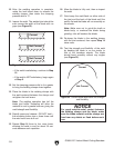
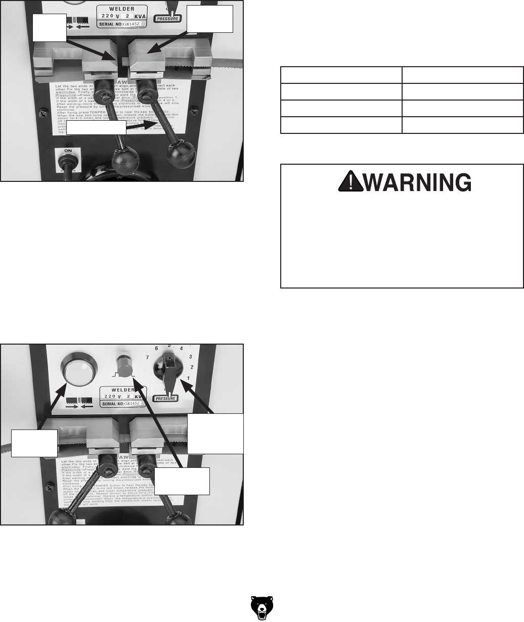
Figure 30. Blade ends in correct position for
welding.
Clamping
Pressure
Dial
Welding
Button
Annealing
Button
6. Set the clamping pressure dial to "0" (see
Figure 30).
Note: As the blade material melts to form the
weld, pressure is applied to the joint by the
welding clamps. The correct amount of pres
-
sure is set with the clamping pressure dial in
a later step.
7. Place the other blade end in the opposite
welding clamp and position it so that it evenly
butts up against the opposing blade end,
then
lock it in place by rotating that lock lever all
the way up, as shown in
Figure 30.
Note: For a good blade weld, it is critical that
the blade ends evenly butt up against each
other.
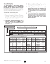
8. Use the chart in Figure 31 and turn the
clamping pressure dial to the correct setting
for the blade.
Burning sparks from the blade welding oper-
ation may be thrown in all directions and
could cause serious personal injury or fire.
When using the blade welder, always protect
yourself from the flying sparks and have fire
extinguishing equipment readily available.
DO NOT weld near flammables.
9. Press and release—DO NOT hold—the weld-
ing button.
Note: There is a limit switch that senses the
electrical resistance between the blade ends.
If there is a adequate amount of welded mate
-
rial, the limit switch will not allow the welding
button to activate the operation again.
Blade Width Pressure Setting
Up to
1
⁄4" 1
1
⁄4" to
3
⁄8" 2–3
Above
3
⁄8" 4+
Figure 31. Blade clamping pressure chart.