


-30- G1022 Series Contractor Saws
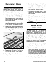
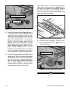
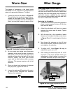
4. Loosen the locking lever (Figure 38) until it
is approximately two-thirds engaged. Make
note of its position and lift it up all the way.
Tighten the rear adjustment screw until the
rear clamp is approximately
1
⁄16'' from the rail.
Move the lock handle back to its two-thirds
position. The rear clamp should just be
touching the rail. If it is too loose or too tight,
lift the handle and turn the adjusting screw in
small increments until the clamp is in its
proper location. NOTE: Do not turn the
adjustment screw unless the lock handle is
in the up position. Damage to the clamp
shoe will result if this step is not observed.
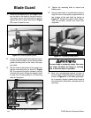
5. Loosen the locking lever and slide the fence
along the rail. Return the fence to its position
at the edge of the miter slot and slowly apply
pressure to the lever. If adjustments are cor-
rect, the fence should square itself before
the rear clamp engages. If the rear clamp
engages before the fence is squared, loosen
the screw one-quarter turn and retest.
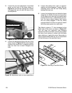
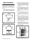
Figure 38. Adjustment bolts for fence parallelism.
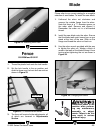
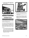
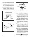
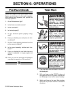
Figure 39. Attaching a sacrificial fence.
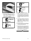
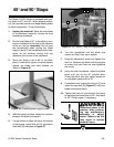
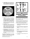
Figure 40. Adjust measurement pointer.
Tip – Attach a piece of
3
⁄4" thick hardwood to the
blade side of the fence shown in Figure 39. This
will keep thin materials from wedging between
the fence and table, and will also protect the
fence from coming in contact with the blade when
dadoing or ripping thin stock.
6. Once the fence is adjusted, check the mea-
surement pointer shown in Figure 40, and
adjust if necessary.
Front Adjustment Screws
Measurement Pointer
Locking Lever