


-34-
G1022 Series Contractor Saws
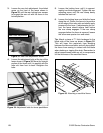
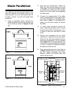
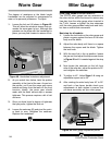
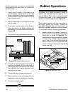
Figure 48. Handwheel resistance adjustment.
Worm Gear
2. As you watch from below, twist the pointer
assembly at the front of the saw. As you turn
the pointer, you’ll see the worm gear move
toward and away from the teeth on the front
trunnion. Ideally, the worm gear should
mesh with the teeth without slop or excess
tightness. This process requires a bit of trial
and error.
3. Once you have found a degree of tightness
that you prefer, tighten the lock nut.
4. Loosen the setscrew (B) and pivot the point-
er back to zero. Retighten the setscrew.
Replace the handwheel.
The degree of resistance at the blade height
handwheel can be adjusted to compensate for
wear or for personal preference. To adjust:
1. Loosen the lock nut (A) shown in Figure 48.
This will allow the eccentric sleeve that sur-
rounds the worm gear to turn. Although this
process can be done with the handwheel in
place, you may find it easier to remove it first.
A
B
Miter Gauge
Initial Step, Model G1022ZF and ZFX:
The ZF/ZFX miter gauge has two setscrews in
the miter slot bar which can be set to remove any
free play from the miter gauge when inserted in
the T-slot. Loosen or tighten the two setscrews
until the miter gauge slides freely back and forth,
but has no side-to-side movement.
Next step for all models:
1. Loosen the lock knob on the miter gauge and
place a square against the face of the miter
body and the blade.
2. Adjust the miter body until there is no space
between the square and the blade. Tighten
the lock knob.
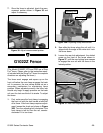
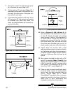
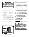
3. With the stop link in the up position, loosen
the jam nut and adjust the stop screw shown
in Figure 49 until it is seated against the stop
link.
4. Now loosen the setscrew on the left front
side of the miter bar, adjust the pointer to 90˚
and retighten the setscrew.
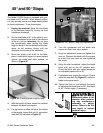
5. To adjust to 45˚, follow Steps 1-4 using an
adjustable square set to 45˚.
6. After rotating the miter body from 45˚ to 90˚
and back a few times, double check your
adjustments at both angles to assure that
you have accurately set your miter gauge.
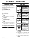
Figure 49. Miter gauge adjustment points.
Stop Link
Jam Nut
Stop Screw