


G1073/G1073Z 16'' Bandsaw -23-
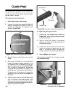
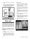
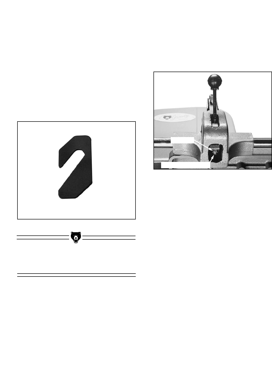
Figure 26. Location of checknut.
Fence Adjustment
Use a tape measure or ruler to measure the dis-
tance from the fence to the blade. To adjust the
front clamping pressure:
1. Lift the lever to the “loose” position.
2. Loosen the checknut below the clamp shoe
shown in Figure 26.
Checknut
Clamp Shoe Hex Bolt
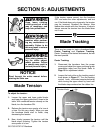
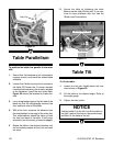
To shift the blade:
1. Loosen the tension on the blade.
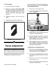
2. Remove the spacers (See Figure 25B)
behind the upper wheel in the desired direc-
tion. Move the upper wheel left or right as
needed, and replace the spacers on the
opposite side from where they were
removed.
3. Readjust the tension. This will secure the
wheel.
4. Repeat guide post bracket adjustments.
Figure 25B. Upper wheel spacer.
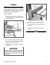
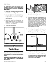
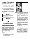
Fence locking is controlled by the lever on the
front of the fence. When the lever is pushed
down, it locks the front and rear of the fence to
the guide rails. The end of the fence nearest to
the operator should lock before the rear.
3. Using a wrench, turn the clamp shoe hex bolt
to adjust the clamping pressure.
4. Push the locking lever down to test the
clamping pressure. The fence should be
tightly clamped to the front rail when the
lever is pushed all the way down.
5. Repeat steps 3-4 until the fence clamps cor-
rectly. Tighten the checknut. Be careful not
to turn the clamp shoe hex bolt or the clamp-
ing pressure will be altered.
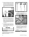
To adjust the rear clamping pressure:
1. Back out the rear clamp adjusting screw sev-
eral turns and put the locking lever in the
locked position as shown in Figure 27.
2. Turn the rear clamp adjusting screw until the
rear clamp just touches the top of the rear
guide rail.
3. Continue to turn the rear clamp adjusting
screw another
3
/4 turn.
4. Test the clamping pressure by loosening and
tightening the locking lever.