


G1066/G1066Z/G1079 Drum Sander -17-
V-Belt
The sanding drums are driven by two V-Belts on
the Models G1066 & G1066Z and one V-Belt on
the Model G1079. The V-Belts must have proper
tension for proper power transmission. Proper
tension is achieved when the V-Belts can be
deflected about
3
⁄4" with moderate finger pressure
at the midpoint between the drum sheaves
(sheaves are integral on the Model G1079) and
the motor sheave. To adjust V-Belt tension,
loosen the motor mounting bolts and slide the
motor accordingly. Ensure that the pulleys stay in
line with each other and tighten the motor mount-
ing bolts. Re-check V-Belt tension and alignment.
To check alignment, ensure that the machine is
on a level floor. Hold a straightedge against the
side of the rear contact drum sheave. The contact
drum and motor sheaves are in alignment when
the straightedge also barely touches the side of
the motor sheave.
To align the sheaves, loosen the motor from the
motor mounting plate and shift the motor in the
desired direction. Tighten the motor mount bolts
and re-check alignment and tension.
If the sheaves will not come into alignment by
adjusting the motor, the motor sheave can be
moved directly along the motor shaft. Loosen the
setscrew on the motor sheave and move it in or
out accordingly.
Always inspect V-belts for damage or deteri-
oration when adjusting for tension or align-
ment. Should you find evidence of cracking,
abrasion or damage from wood chips or
other foreign materials, replace the belt
immediately. Belt breakage could lead to
mechanical damage or operator injury.
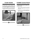
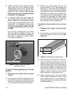
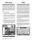
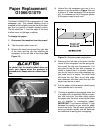
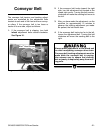
Dust Scoop
Figure 12. Location of dust scoop bolts.
The Model G1066/G1079 is equipped with a dust
scoop located next to the rear sanding drum. The
Model G1066Z features a dust scoop for each
drum. Dust scoops reduce the amount of dust
that accumulates on the workpiece as it travels
through the sander. Dust scoops are adjustable
and should be set approximately
1
⁄32'' above the
bottom of the rear drum for optimum effective-
ness.
To adjust a dust scoop:
1. Unplug the sander from its power source!
2. Place two 2x4’s of equal height under the
rear sanding drum and the dust scoop. Raise
the table until the 2x4’s just touch the drum.
3. Loosen the dust scoop mounting bolts locat-
ed at each end of the scoop as shown in
Figure 12.
4. Move the scoop up or down until it is approx-
imately
1
⁄32'' above the 2x4’s. Some flexing of
the sheet metal assembly may be needed to
get the proper clearance. Retighten the
mounting bolts and remove the 2x4’s.
Dust Scoop
Mounting Bolt