


-20-
G4015Z Lathe/Mill
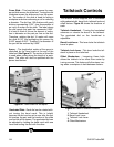
Machine Vise
The Model G4015Z comes supplied with a milling
vise which also serves as the compound for the
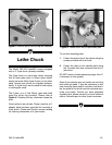
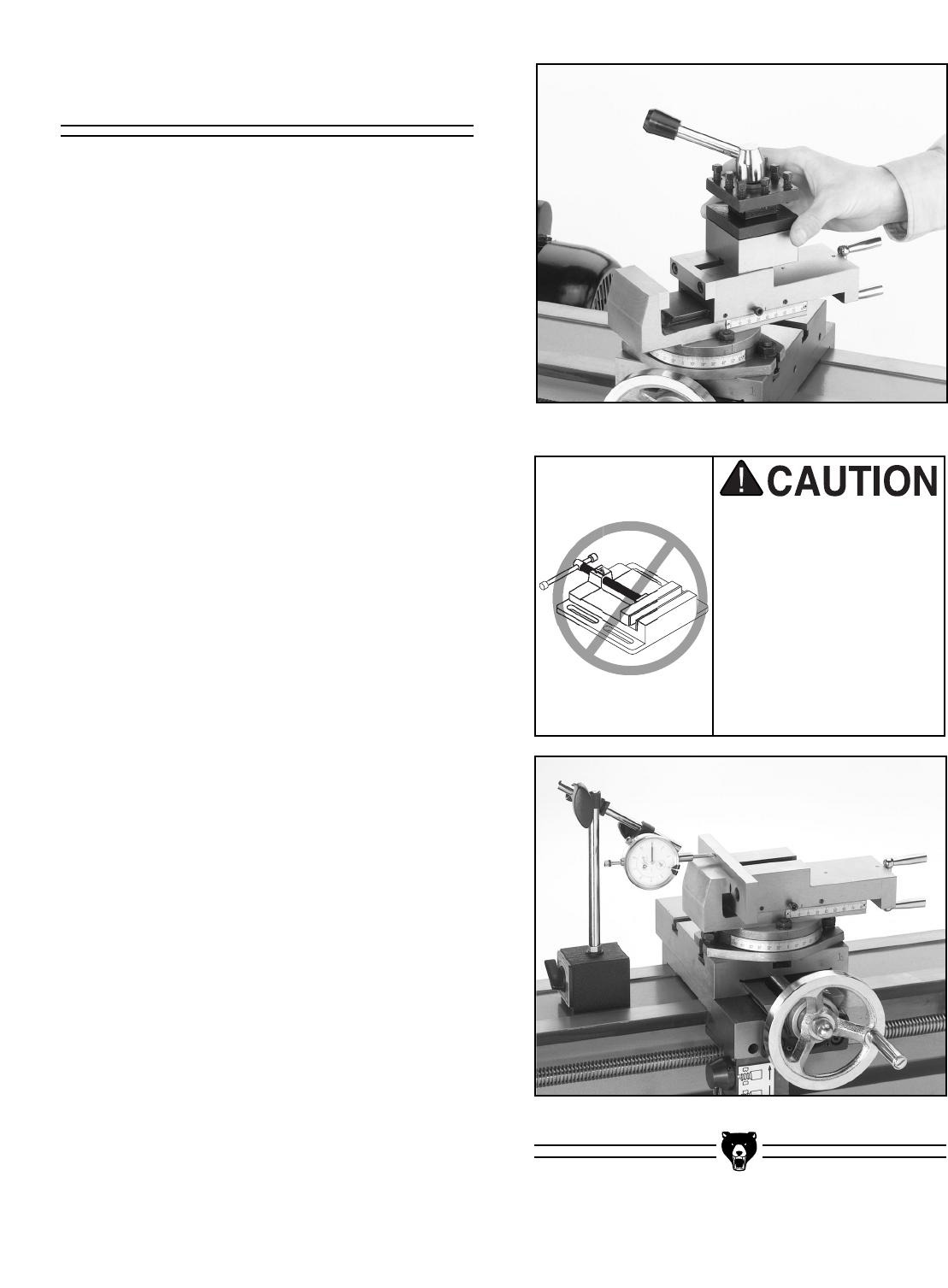
lathe. The 4-way tool post must be removed
before using the vise. Loosen the lock handle
and slide the tool post off of the compound/vise
as in Figure 13.
The milling vise can be aligned to 1 of the 2 axes
of the lathe or at any angle desired. Care must be
given to setting the vise if a precision angle is
needed. The following instructions are given to
make the jaws parallel to the travel of the cross
slide.
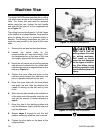
1. Remove the tool post as described above.
2. Loosen the swivel bolts on the
compound/vise so it can swivel freely. Pivot
the compound/vise so the jaws of the vise
are roughly aligned with the cross slide.
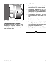
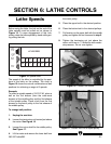
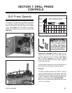
3. Mount the drill chuck into the milling spindle
and secure an indicator into it or, place a dial
indicator mounted to a magnetic base on the
bed as in Figure 14.
4. Position the cross slide and apron so the
indicator point contacts the stationary vise
jaw or a parallel mounted into the vise.
5. Move the cross slide with the hand wheel
and watch the dial. Note the direction the
needle is moving on the dial and by how
much.
6. When the vise has moved so the indicator is
at the other end of the parallel, pivot the vise
one half the amount of motion detected in
step 6.
7. Move the vise to the starting position and
note the difference. Again, pivot the vise one
half the difference.
8. Repeat steps 6 through 8 until the dial
remains stationary when the vise is moved.
9. Tighten the pivot bolts on the base of the
compound/vise.
Figure 13. Sliding the tool post off.
Figure 14. Aligning vise for precision.
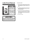
Never use a vise for
milling unless it is rated
for milling machines.
Drill press or bench
vises are not designed
for the rigors of machin-
ing. Vise failure during
a milling operation may
lead to serious personal
injury.