


-38-
G4015 Lathe/Mill
mm
I
II
A
D
24
24
27
30
36
42
60
75
25 30 60 24 30 60
B=120
1.5
1.75
2.5
3
2
0.4 0.4 0.2
0.25
0.3
0.35
0.45
0.75
1.25
0.5
0.6
0.7
1
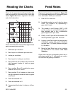
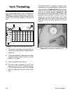
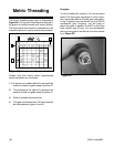
The metric threading gear chart is illustrated in
Figure 49. The layout is listed below to help iden-
tify gears for cutting threads with metric pitches.
The chart below lists threads in millimeters or the
theoretical amount of space one thread occupies.
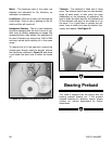
Example:
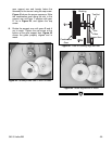
To cut a thread with a pitch of 0.5 mm we would
select a 60 tooth gear and place it in the A posi-
tion; we would select a 30 tooth gear and place it
in the D position and we would use the 60/120
combination gear. However, you will need to
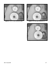
place the gears in position A and D so that they
both contact gear B only. You can accomplish
this by turning gear D so the hub is on the outside
as in Figure 50.
Figure 49.
Rates given in millimeters and inches.
Please note that charts reflect approximate
apron movement per revolution.
1. The column of numbers below D represent the
number of teeth on gears used in position D.
2. The numbers to the right of A represent the
number of teeth on gears used in position A.
3. Field of possible thread pitches.
4. This gear will always have 120 teeth and will
be intermediate to gears A and D.
Metric Threading
1
3
2
4
Figure 50.
Gear D is turned so hub is on outside.