


-21-G4015Z Lathe/Mill
Lathe Speeds
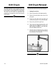
SECTION 6: LATHE CONTROLS
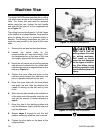
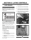
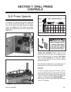
Figure 15. Speed chart.
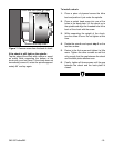
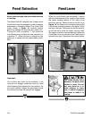
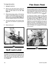
Figure 16. Tension nut shown.
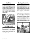
Figure 17. Loosen this nut to adjust pulley.
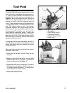
Before using the lathe, the hub on the end of the
lathe spindle must be pulled out as shown in
Figure 15. To ease engagement of this hub,
slowly rotate the lathe spindle by hand while gen-
tly pulling the hub.
the motor pulley.
5. Place the upper belt in the desired position.
6. Place the bottom belt in the desired pulleys.
7. Pull tension on the upper belt with the middle
pulley and tighten the nut loosened in step 3.
8. Tighten the tensioning nut just above the
motor until there is
1
⁄4" deflection with moder-
ate pressure. Do not over tighten.
A
B
C
E
F
D
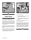
LATHE
SPINDLE
PULLEY
MIDDLE
PULLEY
MOTOR
PULLEY
HUB
PULLED
OUT
A-F A-E A-D B-F C-F B-E C-D
RPM 160 310 375 480 610 880 1380
LATHE S PEEDS
The speed of the lathe is controlled by the posi-
tions of the belts on the pulleys. The chart in
Figure 15 shows the various combinations of belt
positions for achieving a range of 6 speeds.
Example:
To select a spindle speed of 310 R.P.M., place a
belt on the 3rd sheave (from the outer-most
sheave) of the middle pulley and the 2nd sheave
of the spindle pulley. Place a belt from the first
sheave on the motor pulley to the first sheave of
the middle pulley.
To change belt position:
1. Unplug the machine.
2. Loosen the tensioning nut located just above
the motor. See Figure 16.
3. Loosen the nut on shaft for the middle pulley.
See Figure 17.
4. Lift the motor and remove the lower belt from