


Page 7SKU 43378
Assembly
Assembly hardware is located in separate bags. Each bag contains the necessary parts for
each assembly step. Remove all packing and protective material from the Drill Press com-
ponents.
1. Position the Base (B6) on a level oor.
It is recommended to bolt the Base to the oor using appropriate hardware (not
supplied).
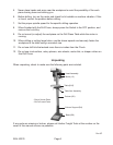
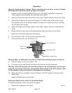
2.
Arm Locking Handle (B16)
Hex Screws (B5)
Table Crank (B8)
Column Support (B4)
Place the Column Support (B4) on the Base, aligning the mounting holes.
3. Insert four large Hex Screws (B5) into the mounting holes and tighten with a wrench.
4. Install the Arm Locking Handle (B16) on the left side of the Table Support (B7). Hand
Tighten.
5. Mount the Table Crank (B8) onto the right side of the Table Support.
Tighten with the Allen wrench. The set screw must be tightened against the at portion
of the screw shaft.
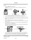
6. Verify that the Column Collar (B19) is square to the Column and that the Set Screw
(B11) is secure (but not overtightened).
The Collar should be positioned so that its rack will slide freely in the collar when the
Table (B15) is rotated around the Column.
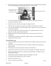
7.
Collar (B2)
Table Clamp (B13)
Arm (B14)
Loosen the Table Clamp (B13) and insert the Table (B15) into the Table Arm (B14).
It may be necessary to pry open the Table Arm opening with a large screwdriver since
it is meant to be a tight t. With the Table in place, retighten the Table Clamp.
CAUTION: Avoid injuries. The next step involves lifting the Head Assembly onto the
Column Tube. The Head Assembly weighs about 55 lb. Have someone help you lift this
assembly into place.
Rev 07i