


SKU 06852 For technical questions, please call 1-800-444-3353. PAGE 10
OPERATING INSTRUCTIONS
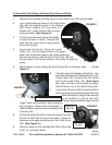
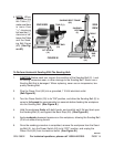
To Install A Sanding Belt:
1. CAUTION: Always turn the Power Switch (53) to its “OFF” position and unplug the
Power Cord (55) from its 110 volt electrical outlet before performing this procedure.
(See Figure B.)
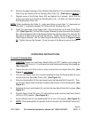
2. Loosen the two Lock Knobs (44) in order to unlock the two Adjust Nuts (44). (See
Figure H, next page.)
3. Turn the two Adjust Nuts (44) counterclockwise to allow the Sanding Belt (2) to be
inserted onto the Sand Belt Frame (40). (See Figure H.)
4. Slide the Sanding Belt (2) fully and evenly onto the Sanding Belt Frame (40). Then,
turn the two Adjust Nuts clockwise to tighten the tension on the Sanding Belt. (See
Figure H.)
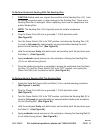
5. Retighten the two Lock Knobs (44), and lock the two Adjust Nuts (44) in place. (See
Figure H.)
6. Plug the Power Cord (55) into a 110 volt electrical outlet, and turn the Power Switch
(53) to its “ON” position. (See Figure B.)
7. Allow sufficient time for the Sanding Belt (2) to turn at full speed. (See Figure H.)
8. NOTE: If the Sanding Belt (2) appears to be too loose on the Sand Belt Frame (40),
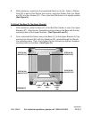
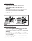
10. Remove the paper backing on the adhesive Sanding Disc (15), and stick the Sanding
Disc firmly and evenly onto the Sanding Disc Plate (16). (See Figure I, page 11.)
11. Replace cover of the Pulley Cover (22) and tighten the 4 screws. Verify that the
pulley cover does not contact the Sanding Disc (15). If it does, you need to adjust
the Sanding Disc Plate (16).
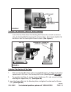
NOTE: When positioning the Table (1), make sure there is more than
1
/
16
” clearance but
less than
1
/
8
” clearance between the Table and the Sanding Disc (15).
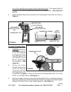
12. Insert the round end of the Support Bar (18) into the hole on the side of the Base
(18). (See Figure G.) Put the Table Support Bracket (9) over the end of the Support
Bar, with the tapered side of the Bracket facing the Sanding Disc (15) and also the
flat side of the Bar lined up with the Set Screw. Tighten the Set Screw (14) on the
Table Support Bracket. Set the Table Support Bracket as shown in Figure J, page
12. Tighten the two Set Screws (14) on the side of the Base to secure the bar.
REV 04b