


SKU 06852 For technical questions, please call 1-800-444-3353. PAGE 9
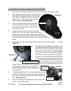
Screw (20)
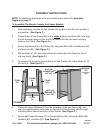
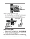
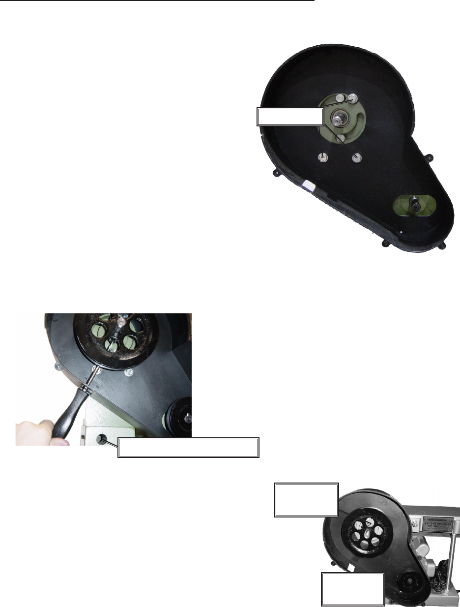
FIGURE E
To Assemble The Pulleys, Sanding Disc Plate, and Table:
1. Remove the 4 screws from the cover on the Pulley Cover (22) and set aside.
2. Line up the three bolt holes on the Pulley Cover
(22) with the threaded holes in the Bracket
(26). Place a Washer (21) over each of 3
Screws (20). Insert a Screw (20) into each
hole and tighten. (See Figure E.)
3. This item is packed with tape on the shafts
to keep the keys in place. Remove the
tape from the upper shaft, being careful
to not lose the key.
4. Loosen the Set Screw (14) on the Large
Pulley (19). Put the Large Pulley on the upper
shaft, with the smaller step on the pulley inside and
with the key lined up with the slot on the Pulley. Be sure
the key stays in the correct position, all the way through the
pulley.
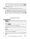
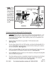
5. Repeat steps 3 and 4 putting the Small Pulley (52) on the lower shaft. ( S e e
Figure F.)
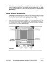
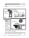
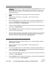
6. Carefully align both pulleys and tighten. Use
a flat head screwdriver through the slot in the
Pulley Cover (22) to tighten the Set Screw
(14) on the Large Pulley (19). (See Figure
G.) Use a hex key (not included) to tighten
the Set Screw (14) on the Small Pulley (52).
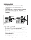
7. Loosen the 4 Screws (48) that hold the Motor
(30) just enough to let the Motor move. Move the
Motor towards the Large Pulley enough
to let the Belt (17) slip on over both
Pulleys. Move the Motor away from the
Large Pulley until the Belt is tight enough so
that, if pushed, it doesn’t move more than
1
/
2
”.
Hold the Motor in place while you retighten the
4 Screws (48).
8. Put the Sanding Disc Plate (16) on the end of the shaft
so that it’s flush with the end of the shaft. Tighten its
set screw, once again using the slot in the Pulley Cover
(22). (See Figure G.)
9. Check to make sure the Sanding Disc Plate (16) is free
of dirt, oil, and other debris.
FIGURE G
hole for Support Bar (18)
FIGURE F
Large Pul-
ley (19)
Small Pul-
ley (52)
REV 04b