


SKU 91130 For technical questions, please call 1-800-444-3353. Page 16
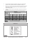
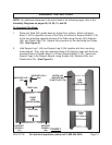
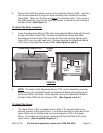
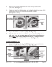
4. Screw a Nut (24B) downward on each of the
eight
Hex Screws (23B). Insert the
Hex Screws downward through the
eight
mounting holes located on the Main
Table (20B). Make sure the Nuts are above the mounting holes. Then, screw a
Nut (24B) upward on each of the eight Hex Screws to secure the Hex Screws to
the Main Table. (See Figure J.)
To Attach The Motor Assembly:
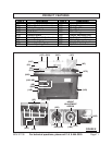
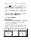
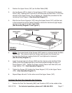
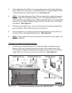
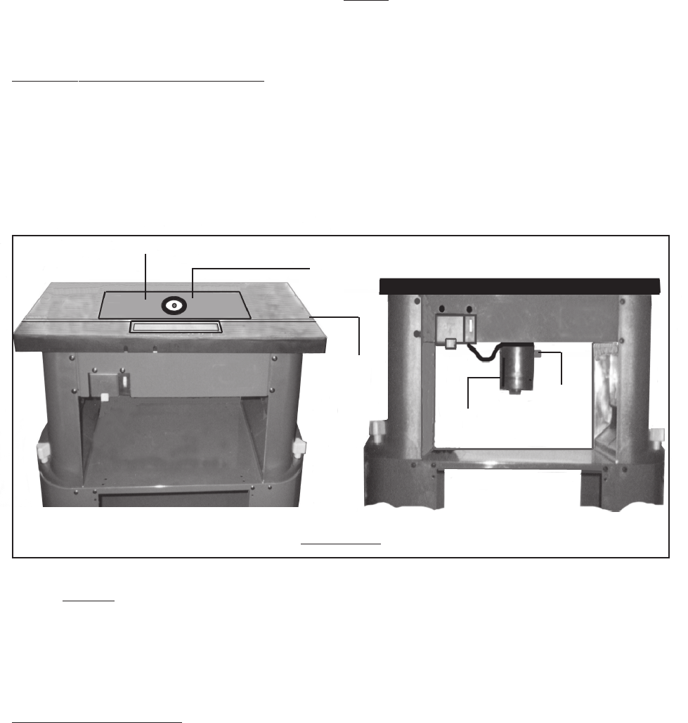
1. Lower the Adjustment Board (17D) with its pre-attached Motor Assembly through
the top of the Main Table (20B). Position the Adjustment Board and Motor
Assembly so that its Power Cord is on the left hand side and the Spindle Lock
Lever (22E) is on the right hand side. Continue lowering the Adjustment Board
until it sits on the eight Hex Screws (23B). (See Figures J and K.)
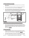
ADJUSTMENT BOARD (17D)
SPINDLE
LOCK
LEVER
(22E)
MOTOR
ASSY.
FIGURE K
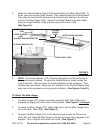
2. NOTE: The height of the Adjustment Board (17D) can be adjusted by inserting
a hex wrench (not included) through the Adjustment Board and adjusting each
Hex Screw (23B) individually. Once adjusted, secure the Adjustment Board to
the Main Table (20B) with four Screws (16D). (See Figures J and K.)
To Attach The Fence:
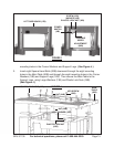
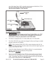
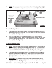
1. The Upper Fence (16C) is supplied with
six
Nuts (11C) already fitted to one
channel (groove) of the Upper Fence. The furthest
two
Nuts on each end of the
Upper Fence are for attaching the two Fence Supports (10C) to the Upper
Fence. The middle
two
Nuts are for attaching the Dust Port Box (24C) to the
Upper Fence. (See Assembly Diagram C.)
MAIN
TABLE
(20B)
..
..
SCREW
(16D)