


SKU 91130 For technical questions, please call 1-800-444-3353. Page 17
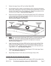
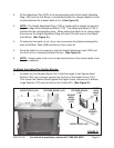
2. Position the Upper Fence (16C) on the Main Table (20B).
3. Use two Screws (9C) to attach a Fence Support (10C) to the back of the Upper
Fence (16C), making sure to use two of the outermost pre-fitted Nuts (11C) in the
channel of the Upper Fence. Do not tighten yet. Repeat this procedure for the
remaining Fence Support (See Assembly Diagram C.)
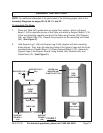
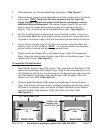
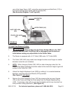
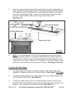
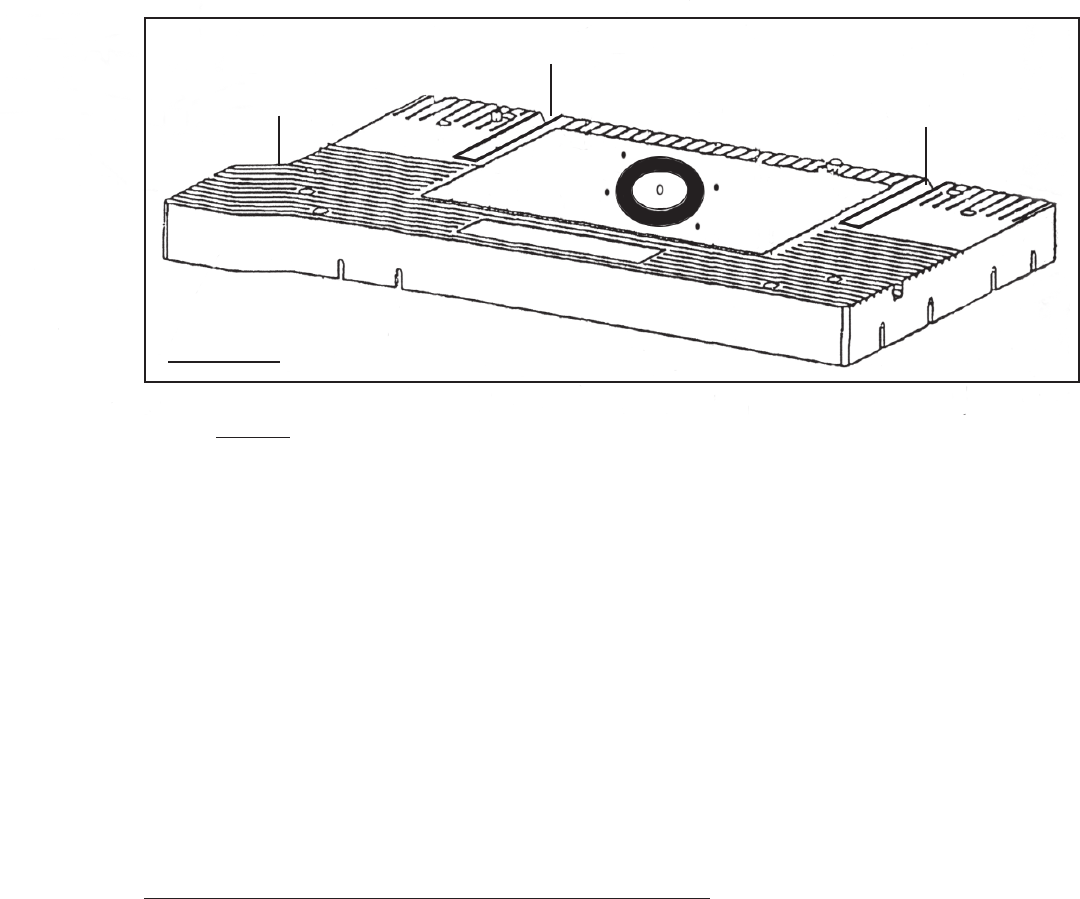
4. Slide the two Fence Supports (10C) along the Upper Fence (16C) until the hole
in the horizontal leg of the Fence Supports is above the
transverse
(right angle)
channel
at the rear of the Main Table (20B).
(See Assembly Diagram C and Figure L.)
TRANSVERSE CHANNEL
TRANSVERSE
CHANNEL
MAIN TABLE
(20B)
FIGURE L
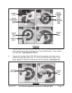
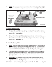
5. NOTE: The screw heads of the Screws (22C) locate in a channel under the Main
Table (20B). This channel holds the Screws and prevents the Screws from
turning when the Fence Locking Knobs (8C) are tightened or loosened.
(See Assembly Diagram C.)
6. Insert the screw head of a Screw (22C) into the channel under the Main Table
(20B) so that the threaded portion of the Screw passes through the hole in a
Fence Support (10C). Tighten the Screw, using a Fence Lock Knob (8C) and
Large Washer (7C). (See Assembly Diagram C.)
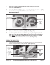
7. Tighten the Screws (9C) holding the Fence Support (10C) to the Upper Fence
(16C). (See Assembly Diagram C.)
8. Repeat Steps #6 and #7 at the other end of the Upper Fence (16C).
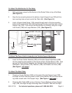
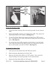
To Attach The Dust Port Assembly And Protector:
1. Position the Dust Port Assembly (26C) and Protector (23C) to the middle of the