


18
Refrigerant Distribution
The distribution system is selected based upon the type of
defrost for that particular system. For each set of liquid /
suction lines a distribution system must be selected.
Liquid solenoids are recommended to be installed at the
evaporator on all systems, particularly systems with long line
runs. The solenoid will prevent continued feed to the
evaporator through the expansion valve when it is not in
operation. A solenoid is mentioned in each of the refrigerant
distribution analysis, and are shipped loose to be installed at
the evaporators.
Heatcraft offers three types of defrost : Off cycle defrost,
Electric defrost and the Priority I hot gas defrost system for
Racks. The type of defrost is generally a matter of either
contractor or owner preference. Typical operation is as
follows:
Off cycle
The off cycle system consists of liquid and suction line ball
valves for circuit isolation, liquid solenoid and defrost
controller. Defrost is initiated by the controller. The liquid
solenoid closes pumping down the circuit, the evaporator fans
remain in operation and room air melts the ice on the coil.
The controller terminates the defrost period after a
predetermined time period and opens the liquid solenoid
putting the system back into refrigeration.
Electric defrost
The electric defrost system consists of liquid and suction line
ball valves for circuit isolation, liquid solenoid, evaporator
heater contactor, heater fusing, evaporator fan motor
contactor and fuses if three phase fans are used, and defrost
controller.
Defrost is initiated by the controller. The liquid solenoid
closes, the evaporator fan contactor opens stopping the fans,
and the defrost heater contactor is energized.
When the defrost heaters warm the coil to a predetermined
level an adjustable defrost termination device within the
evaporator signals the defrost controller to end the defrost
period. A fan delay is provided at the end of each defrost
cycle to allow the evaporator to cool before the fans start.
This also prevents warm air and condensation from being
discharged from the unit. The liquid solenoid opens putting
the system back into refrigeration.
Priority I hot gas defrost
For Racks Only
The Priority I hot gas defrost system consists of liquid and
suction line ball valves for circuit isolation, liquid line solenoid
with by pass check valve, suction solenoid valve, hot gas
solenoid valve, liquid drain solenoid valve, liquid drain
manifold, and defrost controller.
Defrost is initiated by the defrost controller closing the liquid
solenoid and suction solenoid. The hot gas and liquid drain
solenoids open (Unlike typical systems wherein the
condensed liquid from the defrosting evaporator is returned
into the liquid manifold, the Priority I design returns the liquid
to the condenser through a liquid drain manifold).
Hot discharge gas is injected into the suction line at the
parallel rack and flows to the evaporator being defrosted. The
discharge gas will condense into liquid as it flows through the
cold evaporator.
The liquid exits the coil at the distributor side-port, then flows
through the liquid line by pass check valve into the drain
manifold and then returned to the condenser inlet.
The pressure in the condenser is controlled to be below the
returning liquid pressure by a discharge gas regulator valve.
The returning liquid pressure helps in driving refrigerate from
the condenser to the receiver to maintain liquid refrigerant
flows to the refrigerating evaporators. The Priority I system
requires that no more than 20% of the evaporators defrost at
one time.
The discharge gas regulator valve (DDGR) is normally set to
maintain approximately 25 psig differential pressure. The
next part of the Priority I system consists of a small capacity
control system located at the compressor rack. The
discharge gas bypass regulator valve should be set to
maintain the normal suction pressure during normal
refrigeration. There is a desuperheating TXV mounted to
prevent overheating the suction line. The expansion valve
should not require an adjustment as it is preset to maintain
20°F superheat. See page 31 of this manual for more
information on the adjustment of the discharge gas bypass
regulator valve.
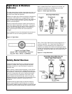
Head pressure control system
Almost all refrigeration systems require some form of year
round head pressure control. This is due to the fixed amount
of condenser surface which has been selected for summer
conditions. During the winter, the condenser is oversized for
the system and low head pressure will result. This will cause
erratic operation of the system.
The following method of head pressure control is considered
the most effective means and has the advantage of
performing well at low outside ambient temperatures. The
disadvantage is the fact that a relatively large quantity
refrigerant must be used to flood the condenser and sufficient
receiver storage must be provided during summer operation.
Head pressure control system consists of a condenser
drain line valve and a discharge bypass valve. In order to
maintain moderate head pressure the condenser drain valve
senses condensing pressure. As condensing pressure falls in
response to lower ambient temperatures, the drain valve will
begin to restrict flow of liquid from the condenser filling
condenser tubes with liquid refrigerant. This results in
decreased surface area causing the discharge pressure to
rise.
When pressure reaches the midpoint setting the valve begins
to open allowing liquid to flow to the receiver. Simultaneously
the discharge bypass valve installed in a line between the
discharge manifold and the receiver maintains minimum
receiver pressure to insure liquid flow.