


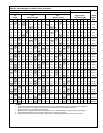
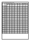

23
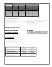
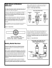
Sight Glass & Moisture
Indicator
The sight glass/moisture indicator helps determine that a unit
has sufficient refrigerant charge and/or when the liquid line
filter drier cores need to be replaced.
Bubbles in the glass may indicate a shortage of refrigerant or
a restriction in the liquid line (i.e. plugged liquid line filter
drier). Moisture typically results from a leak in the refrigerant
system or service operations which open the refrigerant
system to the atmosphere.
Moisture is detrimental because it leads to the formation of
acids which attack components in the system. A change of
color in the indicating dial from green to either chartreuse or
yellow indicates unacceptable moisture in the system in
which case the liquid line filter drier cores need to be
changed.
Upon changing the cores, the indicating dial should return to
green within 12 hours of returning system to operation.
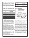
Figure 10. Sight Glass
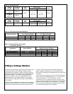
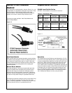
Safety Relief Devices
A refrigerant Safety Relief Device is designed to prevent
pressure in a Vessel from rising above a safe limit when
operating controls fail or when the Vessel is exposed to
excessive heat.
When a Vessel, containing liquid refrigerant, is shut off from
other parts of the system a rise in temperature will cause a
rise in pressure. If the Vessel is completely filled with liquid a
small rise in temperature will cause a rapid and excessive
rise in pressure due to the expansion of the liquid. If the
Vessel contains both liquid and vapor, which is normal for
Refrigerant Receivers, the pressure will rise according to the
temperature-pressure saturation characteristic of the
refrigerant.
If pressure builds up high enough to cause the Vessel to
rupture, large quantities of liquid refrigerant are released.
This causes a sudden reduction of pressure so that the liquid
released is vaporized almost instantly with explosive results.
With a suitable Relief Device installed on the Vessel, the
refrigerant is released at a controlled rate and a safe
pressure is maintained in the Vessel.
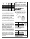
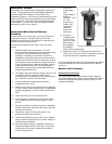
Figure 11. Direct Type Relief Valves
After a “Direct Type” Relief Device has discharged once, it
should be replaced. The “Direct Type” Relief Device is
designed to re-close automatically at a predetermined
pressure, but reliability of the Device to reseal tightly and to
operate at the designed pressure can not be guaranteed after
discharging. Be safe and replace the Device after such an
occurrence.
Figure 12. 3-way Relief Valve