


26
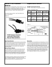
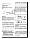
Module Replacement
1. Disconnect power at the fuse box.
2. Remove wiring box from the retainer.
3. Remove the IRR 4000-93 Ring with an IRR P-101
or equivalent retaining ring pliers.
4. Remove the Retainer.
5. Pull out the module by the leads.
6. Install new Module.
7. Verify the voltage rating.
8. Reassemble the Retainer, Ring, and wiring.
Figure 15.
Oil Control
A proper oil control system is essential to insure compressor
lubrication. An oil control system can be very cost effective
alternative to replacing expensive compressors due to loss of
oil. Oil traveling through the system tends to build up in the
evaporator, condenser, and vessels of a refrigeration system.
This causes a lack of oil return to the compressor until finally,
a large amount returns as a “slug” of oil.
A slug of oil down the suction line can be just as damaging to
the compressor as a slug of liquid refrigerant. This delay in
oil return requires an additional amount of oil to be added to
the system, depending on the size of the system, the piping,
the temperatures, the miscibility of the refrigerant/oil mix, and
the refrigerant velocity.
By removing oil from the discharge gas of compressors, not
only is the oil level for each compressor more accurately
controlled, the efficiency of the system is increased. Oil does
not change phase from liquid to gas in a refrigeration system
and therefore makes a very poor refrigerant. Oil also takes
up volume through the system that otherwise could be filled
with refrigerant. Additionally, oil tends to film the condenser
tubing wall lowering heat transfer and as oil and refrigerant
exits the expansion valve, the oil will foam insulating the
evaporator walls and again lowering heat transfer.
IMPORTANT: An oil control system does not
replace the need for proper system design. An oil
control system will drastically reduce the amount
of oil going through the system. Correct piping,
suction traps, and proper sizing of valves, con-
trols, and components must still be implemented
to insure the system will work properly.
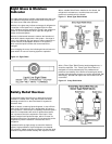
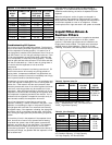
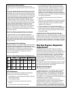
Low Pressure Oil System
This type system is normally used for parallel compressors
and uses three basic components: Oil Separator, Oil
Reservoir, and Oil Level Regulators. The common discharge
is piped to the inlet of the oil separator and the outlet of the oil
separator is piped to the condenser. An oil return line is
brought from the oil separator to the top valve of the oil
reservoir. A vent line is installed to the suction line with a
pressure valve in line to lower the pressure in the reservoir,
making a low pressure oil system. This valve will keep the
reservoir pressure a set pressure above suction depending
on the value of the valve, either 5 or 20 psig to the oil level
regulator. Mechanical oil level regulators are rated for
pressures ranging from 5 to 90 psig differential. The bottom
valve of the oil reservoir is piped to oil level regulators
mounted on the compressor crankcases. These regulators
open to feed oil as the oil level drops and closes as the oil
level raises to the set level. In this manner, the oil level in the
compressor is kept at a constant level. Either one oil strainer
per regulator or one oil filter per separator must be used to
remove debris from the oil.
Figure 16. Low Pressure Oil System
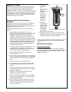
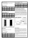
Oil Separators
There are two types of oil separator that may be used in the
Heatcraft parallel racks. One type utilizes the standard
impingement screen. This type separator works by having
the compressed mass flow enter into a large separator
chamber which lowers the velocity and then the atomized oil
droplets collect on the impingement screen surface. As the
oil droplets collect into larger particles they fall to the bottom
of the separator.
The second separator more commonly used is the coalescent
type. This type separator contains a matrix type borosilicate
coalescent filter to do the work impingement screens formerly
did. The exceptionally pure, extremely fine glass fibers
matrices excite the oil molecules to collide into one another
thus agglomerating them into bigger droplets until they are
forced to the outer drain layer of the filter. These droplets fall
to the bottom of the separator reservoir and the oil is then
returned to the compressor.