


28
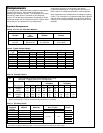
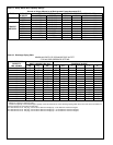
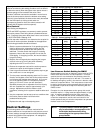
Table 22. A C & R Model Regulators
A C & R CONNECTION OPERATION OIL LEVEL,
MODEL SIZE PRESSURE SIGHT
NO. DIFF, psig GLASS
S-9010 3 BOLT 5 - 30 1/2
S-9010A 4 BOLT 5 - 30 1/2
S-9015 3/4” NPTF F. 5 - 30 1/2
S-9090 3 BOLT 5 - 90 Adjustable
S-9090A 4 BOLT 5 - 90 Adjustable
S-9110 3 BOLT 5 - 30 1/2
S-9120 3 BOLT 5 - 30 1/4 +
S-9130 3 BOLT 5 - 90 Adjustable
S-9190 3 BOLT 30 - 90 Adjustable
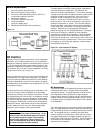
Troubleshooting Oil System
The oil return line should always be checked. Feeling the oil
return line and seeing how often it gets hot is the main way to
tell if the separator is working properly. It is easier if an oil
line sight glass is installed, mainly because if the oil line is hot
you don’t know if it is oil or hot gas causing it to be hot. If the
oil line cycles between hot and cold at least a few times per
hour, the separator is most likely working properly. The float
tends to open and feed a few ounces of oil at a time and shut
until the oil builds back up. If the oil return is cycling there is
no need to drain the separator to look at the float
components.
Always check the oil reservoir level during a service call. Oil
levels in the reservoir will normally vary during periods of
varying loads: compressors shutdown, hot-gas defrost, etc.
This is normal, however if the level is consistently low or high,
the oil system should be checked thoroughly.
Compressor oil levels can be deceiving. It is sometimes hard
to tell if the regulator is feeding oil or if oil is coming down the
suction line. If the reservoir has too much pressure, often
times this pressure will force oil out of the regulator and show
a low level, even though there may be excessive oil in the
compressor. Many times the best way to check the oil in the
compressor is to shut off the oil feeding to the regulator while
the compressor is operating and wait a few minutes. If oil is
pushed out of the regulator or trapped in the motor cavity on
semi-hermetic models, the compressor will overfill.
The oil line sight glass is a good way to see how the
separator is working. Look for movement in the glass. If the
separator is not feeding on single or low pressure systems,
the sight glass will have little or no movement and normally
will appear empty. If the separator is feeding, the sight glass
will show a rush of oil and foam past the glass. Most of the
time, viewing this sight glass can prevent having to open the
system.
To check the oil level in the separator if the separator has a
drain, shut off the oil return line to prevent further feeding,
pump down the system, shut off the system, evacuate the
separator, and drain the oil from the bottom. The separator
should hold the pre-charge amount plus or minus a few
ounces during operation. By looking at the amount above or
below the pre-charge, any problem with the separator or float
can be determined.
Note that there is no way to clean or repair welded oil
separators. If it is determined that the float is clogged or
otherwise malfunctioning, the entire oil separator must be
replaced.
When the refrigerant and/or oil types are changed in a
system, there is the potential for leaks around o-ring seals.
Most elastomers absorb oil and refrigerant and may swell or
shrink when exposed to a new oil or refrigerant. In these
cases replace the o-rings and seals in the system as needed.
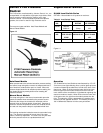
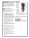
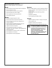
Liquid Filter-Driers &
Suction Filters
A replaceable core liquid filter/drier is supplied as standard
on all Rack units and is an option in all other parallel
systems. A Schrader type access valve is installed in the
flange plate of some models. The liquid cores are always
shipped loose for field installation. (See No. 5 of Leak
Checking, Evacuation, and Start-up section in this manual).
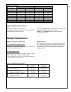
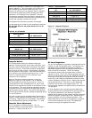
Table 23. Sporlan Valve Co.
SPORLAN NO. OF DESICCANT #
MODEL CORES VOLUME CORE
(CU IN) PART NO.
C-489-(G) 148
C-969-(G) 2 96 RC-4864
C14411-(G) 3 144 RC-4864-HH
C-19211-(G) 4 192 RCW-48
C-4021-(G) 4 192
C-4025-(G) 4 192
“G” indicates flange plate supplied with _” FPT
#“RC__” Standard Core, “RC__HH” Burnout Core
“RCW_” High Water Capacity
Table 24. Alco Controls
ALCO NO. OF DESICCANT #
MODEL CORES VOLUME CORE
(CU IN) PART NO.
STAS-489-T* 148
STAS-969-T 2 96 D-48
STAS-14411-T 3 144 H-48
STAS-19211-T 4 192 UK-48
STAS-19213-T 4 192 W-48
STAS-19217-T 4 192
* “T” indicates Liquid Line Service
#“D” Standard Capacity, “H” High Capacity
”UK” High Capacity, “W” Burnout Block