


20
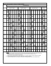
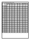
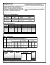
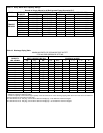
Table 11. Oil Safety Switch
Pressure Alarm
Copeland MFGRS. Model No. Diff. Psi (bar) Circuit
Part No. Cut-In Cut-Out
Sentronic 7 – 9 12 - 14 Yes
085-0062-00 Penn P45NCA-12 No
Ranco P30-5826 Yes
Robertshaw PD21-2502 9 (± 2) 14 No
085-0088-00 Robertshaw PD21-1006 Yes
Penn P45NCB-3 Yes
085-0101-00 Robertshaw LG21-2501 Yes
All controls are Manual Reset type with a 120 second nominal time delay at the rated voltage.
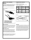
Compressors
The majority of the Heatcraft Parallel systems incorporate the
Copeland compressor. Other brand compressors are
available upon customer request. The compressors are solid
mounted to a base frame or mounted on the refrigerant
receiver. All reciprocating compressors incorporate oil floats.
Crankcase heaters will be installed and wired. Cylinder head
cooling fans will be installed on all low temperature
reciprocating systems or as directed by the specific
compressor manufacturer. A high pressure cutout and oil
failure control are installed and wired for each compressor.
Many compressors are available with unloading for capacity
control. The unloading of a compressor adds many capacity
steps to those normally available to an electronic controller.
Usually, the more steps available the better the load can be
matched.
Copeland Compressors
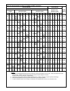
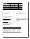
Table 8. 3D / 4D / 6D Solid State Modules
Control Voltage
Model Copeland Copeland T.I.
Number Kit Number Number
Number
115 - 230 Volts
3D-FSM
4D / 6D 998-0524-00 071-0524-00 31AA-1600E
Table 9. Typical Voltage Ranges
Voltage 60 Hertz Rating 50 Hertz Rating
Code Rating Min. Max. Rating Min. Max.
B 230-1 207 253 - - -
C 208/230-3 187 253 200/220-3 180 240
D 460-3 414 506 380/420-3 342 462
E 575-3 518 633 500-3 450 550
K 208/230/460-3 187 506 200/380/400-3 180 440
M - - - 380/420-3 342 462
N 230/460-3 207 506 200/400-3 180 440
U 200-3 180 220 - - -
Refer to voltage rating of specific models.
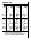
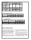
Table 10. Unloader Factors
Model Factors
3D See Copeland Application Bulletin Number AE 21-1278
Moduload - Capacity Control for 3D Compressors
Full Load One Bank Two Bank
Unloading Unloading
Performance HT MT LT HT MT LT HT MT LT
CAPACITY 1.00 1.00 1.00 .50 .50 .50 - - -
4D POWER 1.01 1.03 1.02 .56 .56 .56 - - -
AMPS 1.01 1.03 1.02 .60 .60 .74 - - -
CAPACITY 1.00 1.00 1.00 .70 .70 .70 .36 .36 .36
6D POWER 1.01 1.03 1.02 .70 .71 .72 .40 .42 .43
AMPS 1.03 1.04 1.02 .75 .77 .84 .55 .60 .72
Multiply compressor rating data by above factors when used with blocked suction unloading.
Refer to Copeland AE 17-1287 for Demand Cooling Restrictions on unloading.