


8
• When brazing refrigerant lines, an inert gas
should be passed through the line at low
pressure to prevent scaling and oxidation
inside the tubing. Dry nitrogen is preferred.
• Use long radius ell’s for lower pressure drop.
• Provide expansion loops in long straight
refrigerant lines that are subject to expansion
and contraction. See Expansion Loops in
this manual for more information.
Refrigerant Line Insulation
• Insulate suction lines from the evaporators to
the parallel unit with minimum 3/4" thickness
closed-cell type insulation on low temperature
circuits. Insulate suction lines on medium
temperature circuits with minimum 1/2" thick
insulation to prevent condensation.
• Long liquid lines run in areas exposed to high
temperatures should be fully insulated with
minimum 1/2" insulation.
• Suction and liquid lines should never be taped
or soldered together.
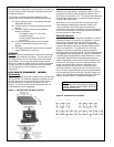
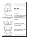
Refrigerant Line Support
• Strap and support tubing to prevent excessive
line vibration and noise. All tubing clamps
should have an insulating material (i.e. Hydra
Sorb bushing) to prevent metal to metal
contact.
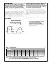
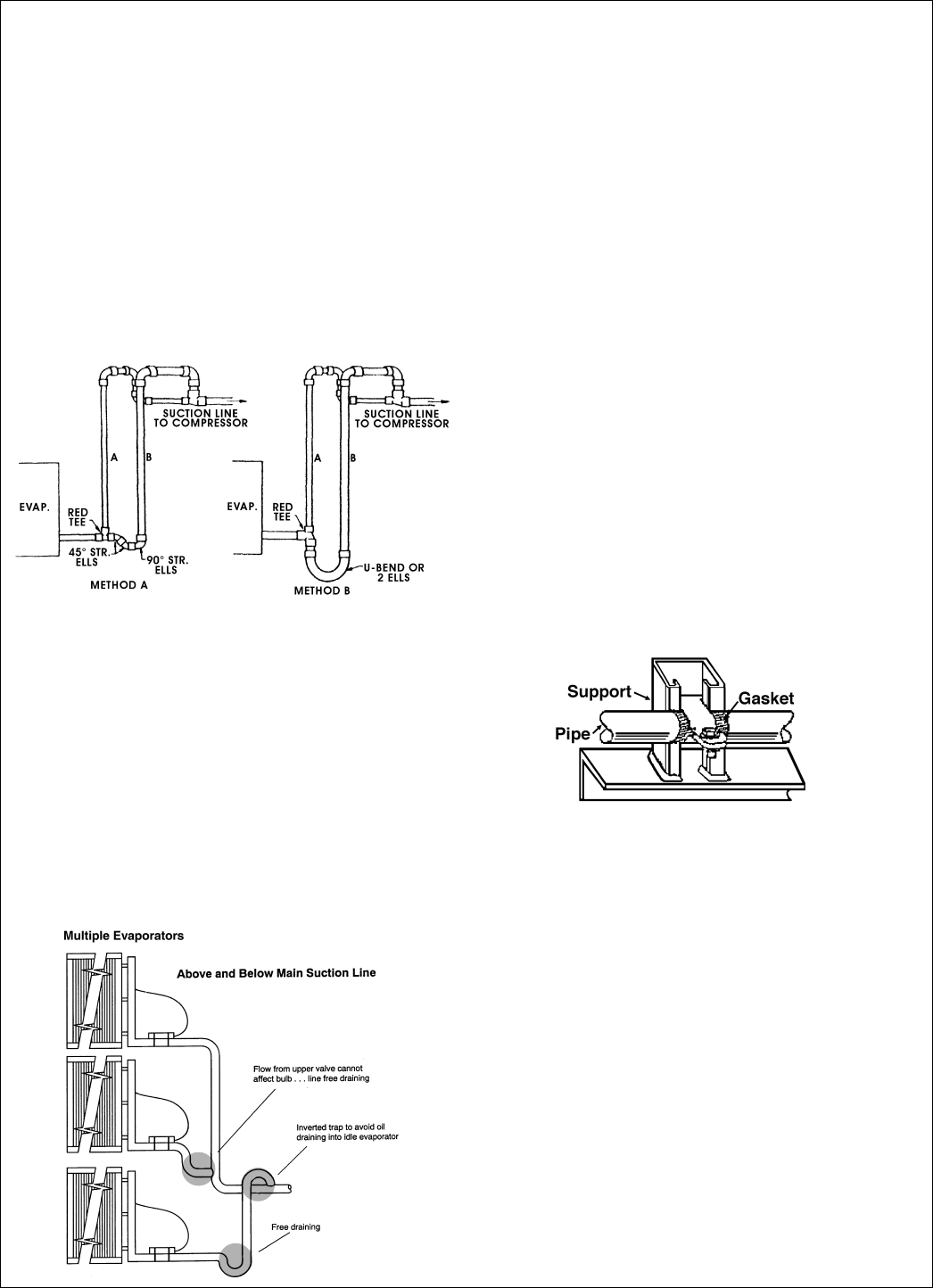
Figure 8. Pipe Support
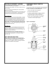
• In systems equipped with capacity control
compressors, or where multiple compressors
are used with one or more compressors
cycled off for capacity control, double suction
risers should be installed. See Figure 6
below. The two lines should be sized so that
the total cross-section area is equivalent to
the cross section area of a single riser that
would have both satisfactory gas velocity and
acceptable pressure drop at maximum load
conditions. The two lines normally are
different in size, with the larger line trapped
as shown. The smaller line must be sized to
provide adequate velocities and acceptable
pressure drop when the entire minimum load
is carried in the smaller riser.
Figure 6. Double Suction Risers
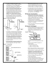
• In operation, at maximum load conditions gas
and entrained oil will be flowing through both
risers. At minimum load conditions, the gas
velocity will not be high enough to carry oil up
both risers. The entrained oil will drop out of
the refrigerant gas flow and accumulate in the
"P" trap forming a liquid seal. This will force
all of the flow up the smaller riser, thereby
raising the velocity and assuring oil circulation
through the system.
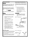
• When connecting more than one suction line
to a main trunk line, connect each branch line
with an inverted trap. See Figure 7 below.
Figure 7. Inverted Trap
• Straight runs should be supported near each
end.
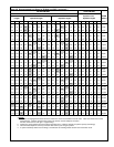
• Long runs require additional supports. A
general guide is
* 3/8" to 7/8" every 5 feet.
* 1 1/8" to 1 3/8" every 7 feet.
* 1 5/8" to 2 1/8" every 10 feet.
• When changing directions, supports should be
placed a maximum of 2 feet in each direction.
• Piping attached to a vibrating object (such as a
compressor or compressor base) must be
supported in such a manner that will not
restrict the movement of the vibrating object.
Rigid mounting will fatigue the copper tubing.
• Use only a suitable silver solder alloy on
suction and liquid lines.
• Limit the soldering paste or flux to the
minimum required to prevent contamination of
the solder joint internally. Flux only the male
portion of the connection, never the female.
After brazing, remove excess flux.