


11
English
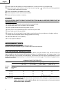
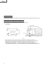
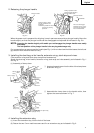
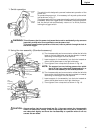
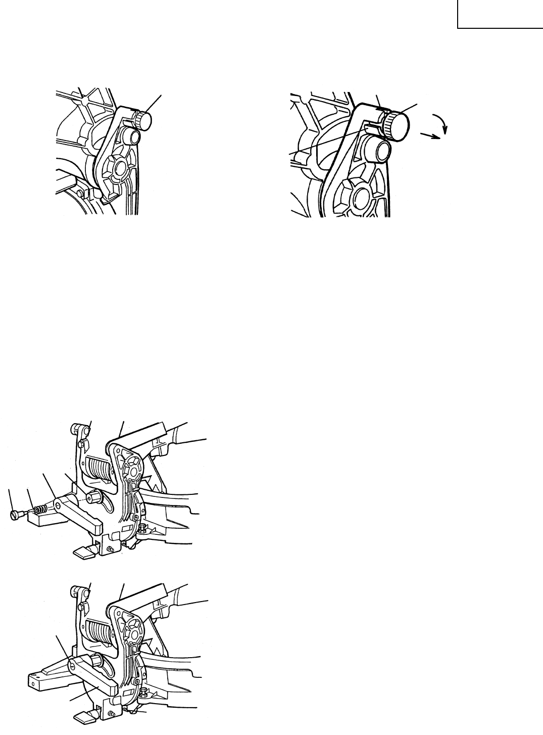
2. Releasing the plunger handle
Fig. 5-a Fig. 5-b
When the power tool is prepared for shipping, its main parts are secured by a plunger handle. Move the
handle slightly so that the plunger handle can be disengaged and adjusted as indicated in Fig. 5-b.
NOTE: Lowering the handle sloghtly will enable you to disengage the plunger handle more easily
and safely.
The lock position of the plunger handle is for carrying and storage only.
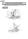
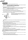
For transportation purpose, grasp the handle (see Fig. 1) with one hand and hold the base at the left end
grip section with the other hand to carry.
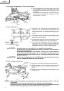
3. Installing the dust bag, miter handle, extension wing, stock stop and vises.
(The extension wing and stock stop are optional accessories).
Attach the dust bag, miter handle, extension wing, stock stop and vise assembly as indicated in Fig. 1
and Fig. 2.
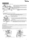
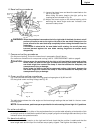
(1) Assembly of clamp lever
q Insert spring and screw into the hole of the clamp lever
as shown in Fig. 6.
w Assemble the clamp lever to the handle collar, then
tighten the screw as shown in Fig. 7.
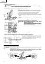
4. Installing the extension stay
(1) Insert the extension stay into the hole of the base.
(2) Fasten the two 5 mm machine screws and fix an extension stay as indicated in Fig. 2.
Plunger Handle
Plunger Handle
Clockwise
Pull out to disengage.
Rotate the knob 1/4 turn
and fit the pin stoppers
into the shallow slot.
Fig. 6
During transport, fit the
plunger handle into the
deep slot.
NOTE:This position is not be
used for any cutting
operation.
During operation fit the
plunger handle stoppers
into the shallow slot.
Fig. 7
Clamp Lever
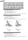
5 mm Hex. soc. hd. cap bolt (C)
(Stopper for 0°)
Screw
Handle
Collar
Clamp
Lever
Screw Spring