


16
English
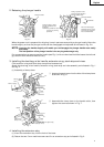
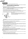
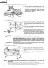
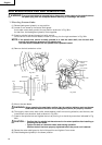
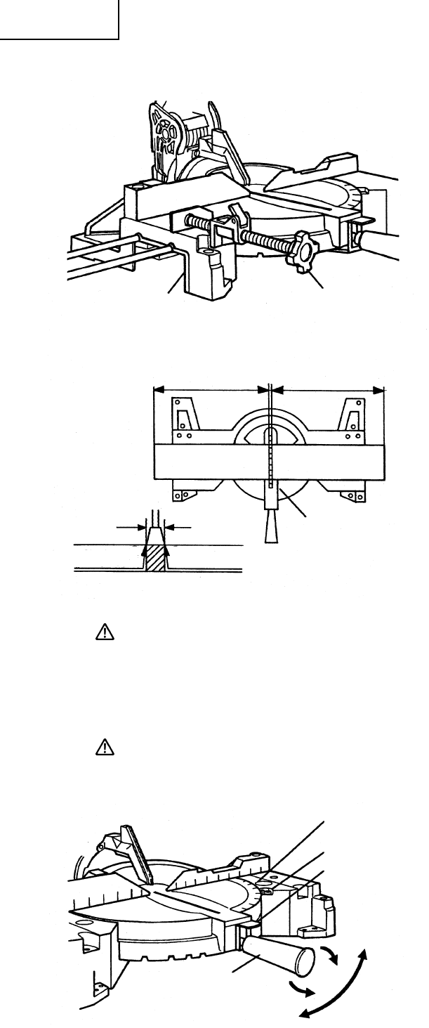
3. Using the vise assembly (Optional accessory)
(1) The vise assembly can be mounted on either the
left side base or the right side base, and can be
moved back and forth according to the width of the
workpiece.
Insert support of vise assembly into the hole located
on either the left side base or the right side of the
base as shown in Fig. 20.
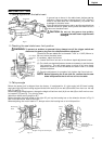
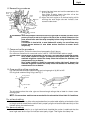
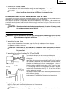
4. Cutting Operation
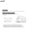
(1) As shown in Fig. 21 the width of the saw blade is the
width of the cut. Therefore, slide the workpiece to the
right (viewed from the operator’s position) when
length b is desired, or to the left when length a is
desired.
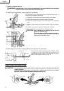
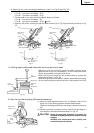
(2) Once the saw blade reaches maximum speed, push
the handle down carefully until the saw blade
approaches the workpiece.
(3) Once the saw blade contacts the workpiece, push the
handle down gradually to cut into the workpiece.
(4) After cutting the workpiece to the desired depth, turn
the power tool OFF and let the saw blade stop
completely before raising the handle from the
workpiece to return it to the full retract position.
CAUTION: * Increased pressure on the handle will not increase the cutting speed.
On the contrary, too much pressure may result in overload of the motor and/or
decreased cutting efficiency.
* If the handle is pressed down with excessive or lateral force, the saw blade may
vibrate during the cutting operation and cause unwanted cutting marks on the
workpiece, thus reducing the quality of the cut. Accordingly, press the handle down
gently and carefully.
WARNING: * Confirm that the trigger switch is turned OFF and the power plug has been removed
from the receptacle whenever the tool is not in use.
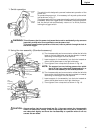
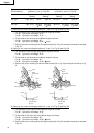
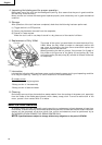
5. Miter cutting procedures
(1) Loosen the miter handle and push the spring plate.
(2) Adjust the table until the indicator aligns with the
desired setting on the miter angle scale as shown in
Fig. 22.
(3) Re-tighten the miter handle to secure the table in the
desired position.
NOTE: * Positive stops are provided at the right and left of the 0° center setting, at 15°, 22.5°, 31.6°, and
45° settings.
Check that the miter angle scale and the tip of the indicator are properly aligned.
* Operation of the power tool with the miter angle scale and indicator out of alignment, or with
the miter handle not properly tightened, will result in poor cutting precision.
Fig. 20
Vise
AssemblyBase
(Front View)
Adjusting Line
ab
Marking
(pre-marked)
Marking
(pre-marked)
ab
a
b
Table Insert
Fig. 21
Workpiece
Fig. 22
Miter Angle
Scale
Indicator
Spring
Plate
Tighten
Turn the
Table
Loosen
Miter Handle