


15
English
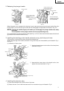
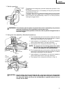
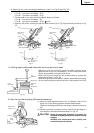
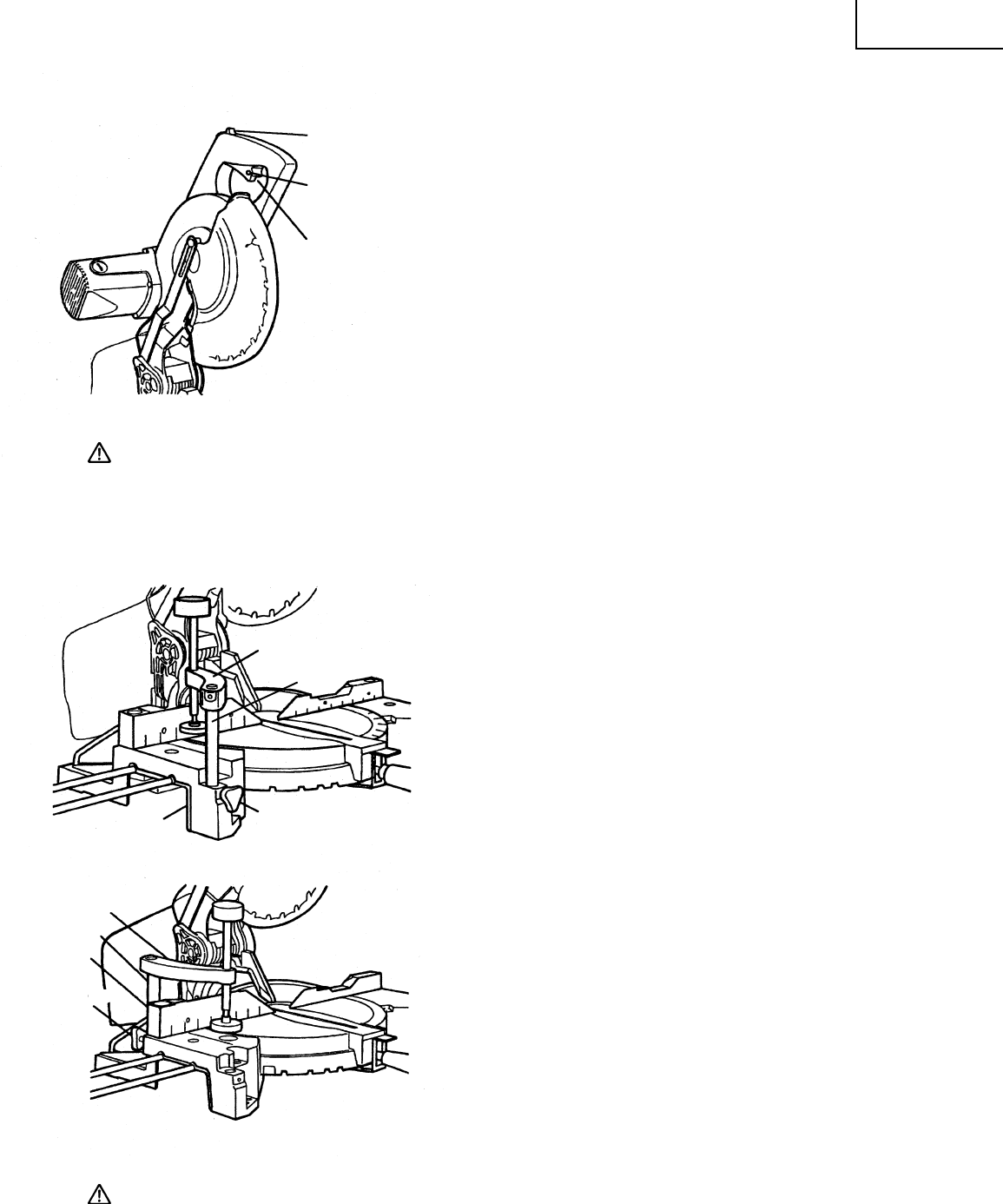
Fig. 17
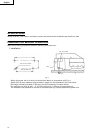
1. Switch operation
The switch lock is designed to prevent inadvertent operation of the
power tool.
To operate the power tool, it is necessary to first push up the switch
lock as shown in Fig. 17.
The trigger switch will not operate unless the switch lock has been
pushed up. When the trigger switch is released, the power goes off
and the switch lock automatically returns to its initial position,
locking the trigger switch.
WARNING: This will ensure that the power tool cannot be turned on accidentally or by someone
(especially a child) who is not qualified to use the power tool.
To prevent unauthorized operation of this tool, insert a padlock through the hole in
the switch trigger.
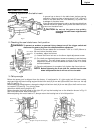
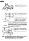
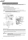
2. Using the vise assembly (Standard accessory)
(1) The vise assembly can be mounted on either the left side
base or the right side base, and can be raised or lowered
according to the height of the workpiece.
q Insert support of vise assembly into the hole located on
either the left side base or the right side base.
w Then tighten 5 mm clamp bolt as shown in Fig. 18.
NOTE: The support has two locking grooves into which
the tip of the 5 mm clamp bolt is designed to fit, to
lock the vise assembly in the desired position.
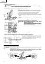
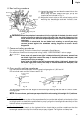
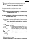
(2) The vise assembly can be mounted on either the left side
fence or the right side fence, and can be raised or lowered
according to the height of the workpiece.
q Insert support of vise assembly into the hole located on
either the left side fence or the right side fence.
w Then tighten 5 mm clamp bolt as shown in Fig. 19.
CAUTION: Always confirm that the motor head (see Fig. 1) does not contact the vise assembly
when it is lowered for cutting. If there is any danger that it may do so, loosen the 5
mm clamp bolt slightly and move the vise assembly to a position where it will not
contact the saw blade.
Switch
Lock
Hole
Trigger
Switch
Base
5 mm
Clamp Bolt
Vise
Assembly
Support
Fig. 18
5 mm
Clamp Bolt
Fence
Support
Vise
Assembly
Fig. 19