


13
English
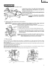
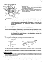
Fig. 9
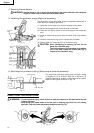
Fig. 10
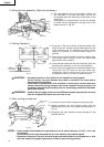
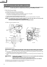
Fig. 12
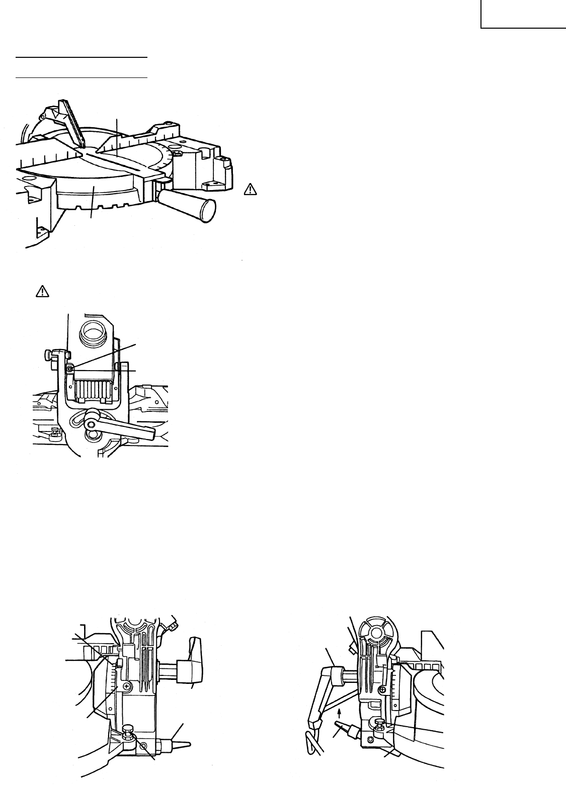
BEFORE CUTTING
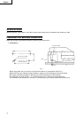
1. Cutting a groove on the table insert.
A groove has to be cut in the table insert, before starting
operation. Secure a piece of wood about 5-1/8" (130 mm)
wide to the table with the vise assembly, to prevent the
breakage of the table insert.
After the switch has been turned on and the saw blade has
reached maximum speed, slowly lower the handle to cut a
groove on the table insert.
CAUTION: Do not cut the groove too quickly;
otherwise the table insert might become
damaged.
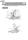
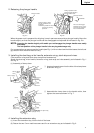
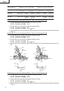
2. Checking the saw blade lower limit position
WARNING: To prevent an accident or personal injury, always turn off the trigger switch and
disconnect the power plug from the receptacle before adjustment.
Check that the saw blade can be lowered 1-1/32" to 1-3/32" (26 mm to
28 mm) below the table insert.
If necessary, adjust as follows:
(1) Loosen the 6 mm lock nut on the 6 mm depth adjustment screw.
(2) Turn the 6 mm depth adjustment screw as necessary to set the lower
limit position. The saw blade goes up when the 6 mm depth
adjustment screw is turned clockwise and down when it is turned
counterclockwise.
(3) Once the adjustment is complete, fully tighten the 6 mm lock nut.
NOTE: Before tightening the 6 mm lock nut, confirm that the saw
blade is adjusted so that it will not cut into the table.
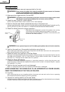
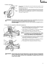
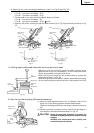
3. Oblique angle
Before the power tool is shipped from the factory, it is adjusted for 0°, right angle, left 45° bevel cutting
angle and right 45° bevel cutting angle with the 6 mm bolt (A), 6 mm bolt (B) and the 5 mm hex. soc. hd. cap
bolt (C) (see Fig. 7).
When changing the adjustment, change the height of the 6 mm bolt (A), 6 mm bolt (B) or the 5 mm hex. soc.
hd. cap bolt (C) (see Fig. 7) by turning them.
(Maximum bevel cutting angle is 45°).
When changing the bevel angle to the right 45°, pull up the locating bar on the direction shown in Fig. 12
and incline the motor head to the right.
When adjusting the motor head to 0°, always return the locating bar to its initial position.
Table Insert
Table
d
6 mm Depth
Adjustment
Screw
6 mm Lock
Nut
Fig. 11
6 mm Bolt (A)
(Stopper for right 45° bevel angle)
Locating
Bar
Clamp Lever
Indicator
Bevel Angle
Scale
6 mm Bolt (B)
(Stopper for left 45°
bevel angle)
5 mm Hex. soc. hd. cap bolt (C)
(Stopper for 0°)
Locating
Bar
Pull
Up
Clamp
Lever