-24-
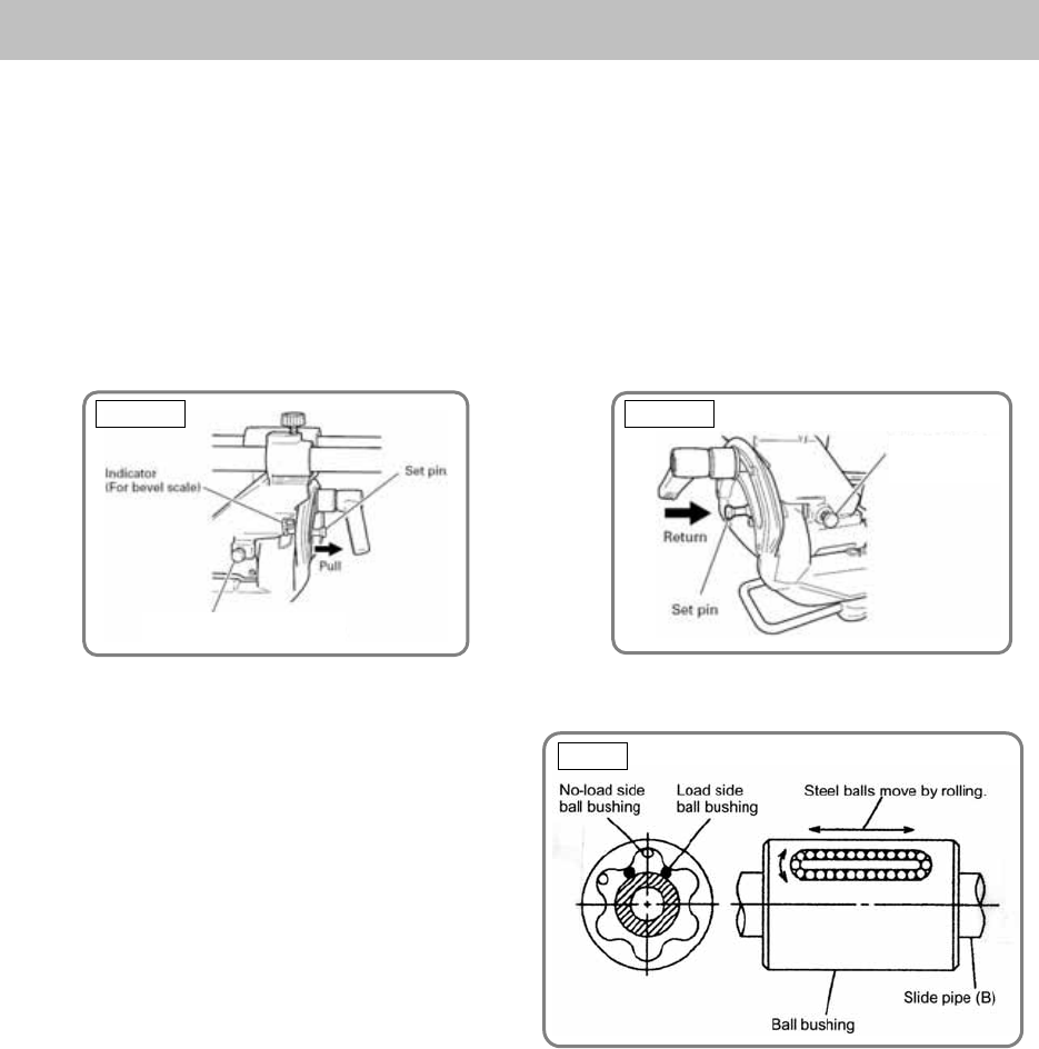
1. Bevel angle adjustment
Before shipping from the factory, the height of 8-mm bolts (A) and (B) is adjusted so that the saw blade
section (head) will stop at 0° (right angle), and 45° to the left. To change the head stop positions, instruct
the customer to adjust the height of 8-mm bolts (A) and (B) by turning them.
CAUTION:
If there is any clearance between the tip of 8-mm bolt (A) (stopper for 0°) and the fixing pin, the
angle of the saw blade relative to the upper surface of the turn table may not be an exact right angle.
(8-mm bolts (A) and (B) are located at the holder (A).) Press down on holder (A) and lock it in
position with the clamp lever so that there is no clearance between the fixing pin and 8-mm bolt (A).
2. Ball bushing (Linear bearing)
(1) Structure of the ball bushing
The ball bushing is commonly called a linear
ball bearing. Inside the bearing is elongated
guide grooves in which steel balls circulate
and roll when a load is applied. (as indicated
by the arrow marks in Fig. 34). This type of
device is widely used in automated machine
tools. The advantage of the ball bushing is
that its friction coefficient remains largely
unchanged even when the load is increased,
ensuring smooth sliding movement.
In addition, slide pipe (B), made of bearing steel and heat treated to a high degree of hardness (HRC 62
to 65), is highly resistant to wear.
Sales persons should have a good understanding of the structure and rugged characteristics of this
exceptional mechanism to enhance sales promotion.
(2) Lubrication
If it is necessary to replace the ball bushing, apply approximately 2 grams (0.1 oz) of grease (Nippeco
SEP 3A) on the steel balls and within the guide grooves of the new ball bushing. If grease is not applied,
it will shorten the service life of the ball bushing, and subsequent abrasive contact between the steel
balls and slide pipe (B) will cause abnormal noise during slide cutting operations. Customers should be
instructed to thoroughly remove sawdust and other foreign matter from slide pipe (A) and slide pipe (B)
and liberally coat them with machine oil at least once a month.
ADJUSTMENT OF COMPONENTS
Fig. 33-bFig. 33-a
Fig. 34
8 mm bolt (B)
(Stopper for left 45° bevel angle)
8 mm bolt (A)
(Stopper for 0°)


