-42-
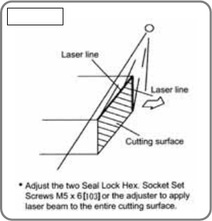
of the laser line. (Repeat this operation 3 or 4 times depending on
the adjusting conditions of the laser marker.) Refer to the above
"(1) Construction of laser marker and functions of each
component" for the relation between the two Seal Lock Hex.
Socket Set Screws M5 x 6 [103] and the laser line.
4) To check the accuracy of the Laser Marker [107], move the Laser
Marker [107] horizontally using the Adjuster [88] again and
check that the laser beam is applied to the entire cutting surface.
If the laser beam is applied to the cutting surface in parallel, the
fine fuzz reflects the laser beam and the entire cutting surface
becomes bright.
5) Make a right-angle ink line on the workpieces of 20 mm (13/16")
in height and 150 mm (5-15/16") in width and 60 mm (2-3/8") in
height and 150 mm (5-15/16") in width respectively. Adjust the
laser marker and perform cutting. If the ink line matches the
cutting position, the accuracy adjustment is completed. (Visually
check that the laser marker accuracy is 0.35/100 or less for both
the squareness with the base surface and the squareness with
the fence surface.)
Fig. 58-c


