


-38-
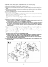
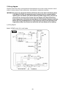
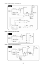
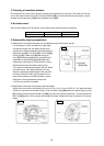
3. Checking of insulation distance
Do not remove too much of the insulation coating at the internal wire connection. Take care not to let the
core of the internal wire stick out the Connector 50092 [168] or let the internal wires get caught in a joint
between the Housing Ass’y [155] and the Handle Cover [164].
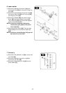
4. No-load current
After no-load operation for 30 minutes, the no-load current values should be as follows.
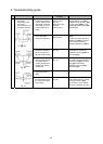
Voltage 110 V, 120 V 220 V, 230 V, 240 V
No-load current 4.7 A max. 2.5 A max.
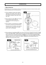
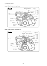
5. Reassembly requiring adjustment
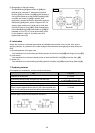
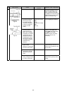
(1) Adjustment of squareness between the saw blade (dummy disc) and the fences
It is necessary to check and adjust the right-angle
orientation between the saw blade (dummy disc)
and the fence after disassembly and replacement of
the Base Ass’y [56], Turn Table [13], Fence (A) [55],
Fence (B) [47], Holder (A) [124] and Hinge (A)
Ass’y [87] and after disassembly, reassembly and
adjustment of the Ball Bushing [114]. Adjust the
squareness (rated value 0.15/100 mm) by moving
the fences along the saw blade (dummy disc).
First, adjust the squareness between the saw blade
and either fence. Then adjust flatness of the two
fences by applying a straight edge to the right and
left fence surfaces. Finally, apply a square to the
fence surface that has not been checked yet and
make sure it forms squareness (rated value
0.15/100 mm) with the saw blade.
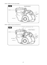
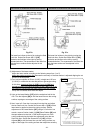
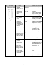
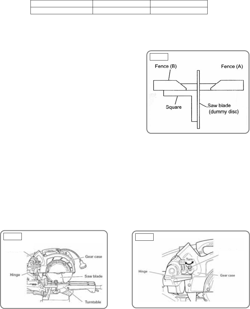
(2) Adjustment of the lower limit position of the saw blade
Adjust the unit so that the saw blade (216 mm (8-1/2")) is 10 to 11 mm (13/32" to 7/16") below the base
surface (or top surface of the table insert). Lower the Gear Case [198] (head) and make Hinge (A) Ass’y
[87] contact with the Nylock Bolt M8 x 25 [190] for lower limit position adjustment. Turn the Nylock Bolt
M8 x 25 [190] with a 13-mm wrench and change the height to adjust the lower limit position of the saw
blade.
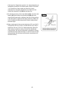
Fig. 54
Fig. 53
Fig. 52
8-mm depth
adjustment bolt
8-mm depth
adjustment bolt