


-21-
grain) are better than those on the sides marked ( B ).
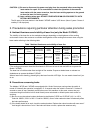
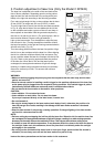
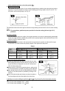
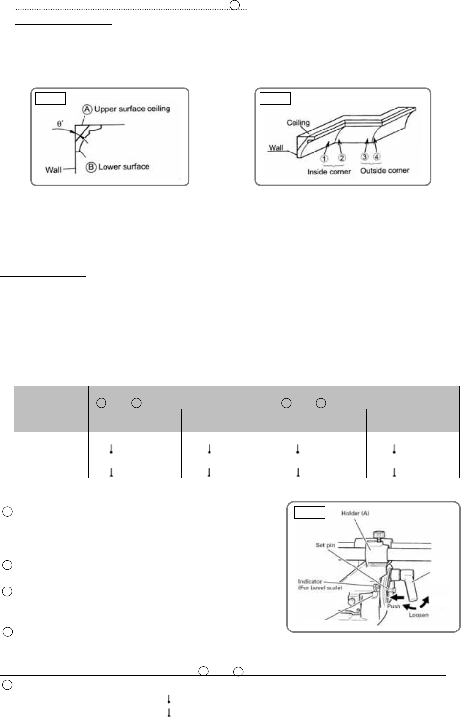
(9) Crown molding cutting
This machine can cut two types of crown molding workpieces by combining the miter and bevel cutting
operations. Figure 25 shows two common crown molding types having angles of (θ) 38° and 45°. For
the typical crown molding fittings, see Fig. 26.
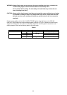
The table below shows the miter angle and the bevel angle settings that are ideal for the two crown molding
types.
NOTE : For convenience, positive stops are provided for the miter setting (left and right 31.6°)
positions.
For miter cut setting
If the turn table has been set to either of the angles described, move the turn table adjusting side handle
a little to the right and left to stabilize the position and to properly align the miter scale and the tip of the
indicator before the operation starts.
For bevel cut setting
Move handle on miter section to the right and left and check that the position is stable and the angle
scale and the tip of the indicator are properly aligned. Then tighten the clamp lever.
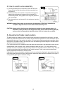
To process crown molding at positions
1 and 4 in Fig. 26.
To process crown molding at positions
2 and 3 in Fig. 26.
Type of
crown
molding
Miter angle
setting
Bevel angle
setting
Miter angle
setting
Bevel angle
setting
45° type Right 35.3°
( mark)
Left 30°
( mark)
Left 35.3°
( mark)
Left 30°
( mark)
38° type Right 31.6°
( mark)
Left 33.9°
( mark)
Left 31.6°
( mark)
Left 33.9°
( mark)
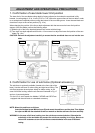
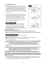
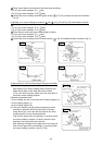
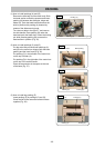
30° and 33.9° left slant setting method
1 Loosen the clamp lever and slant to the left a little at a time
while pushing the set pin into the main unit. At this time, the
set pin will enter one step and fit into the 30° left slant and
33.9° left slant setting slots.
2 With the set pin in the slot as described above, setting to the
30° left slant position is possible by pushing to the right side.
3 Also, with the set pin in the slot as described above, setting
to the 33.9° left slant position is possible by pushing to the
left side.
4 Look at the bevel scale and indicator to recheck whether or
not the settings match and then tighten the clamp lever.
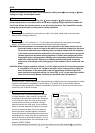
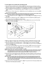
(1) Setting to cut crown moldings at positions
1 and 4 in Fig. 26 (see Fig. 28; tilt the head to the left):
1 Turn the turn table to the right and set the miter angle as follows:
* For 45° type crown moldings: 35.3° ( mark)
* For 38° type crown moldings: 31.6° ( mark)
Table 8
Fig. 27
Fig. 26Fig. 25
Bevel scale
Tighten
Clamp
lever